ESP32 Tutorial 50/55 - Control RGB LED from anywhere in the world | SunFounder's ESP32 kit
In this tutorial, we will learn how to control the color of an RGB LED using the ESP32 microcontroller over Wi-Fi, utilizing the MQTT protocol and Adafruit IO service. This setup allows you to change the color of the RGB LED from anywhere in the world, providing a practical application of IoT technology. We will also explore how to use sliders and a color picker to select the desired color.

The ESP32 is a powerful microcontroller that has built-in Wi-Fi and Bluetooth capabilities, making it ideal for IoT projects. In this build, we will connect an RGB LED to the ESP32 and control its color through an MQTT broker provided by Adafruit. The tutorial will guide you through the hardware setup, wiring instructions, and the code necessary to make everything work seamlessly (in video at 00:00).
Hardware Explained
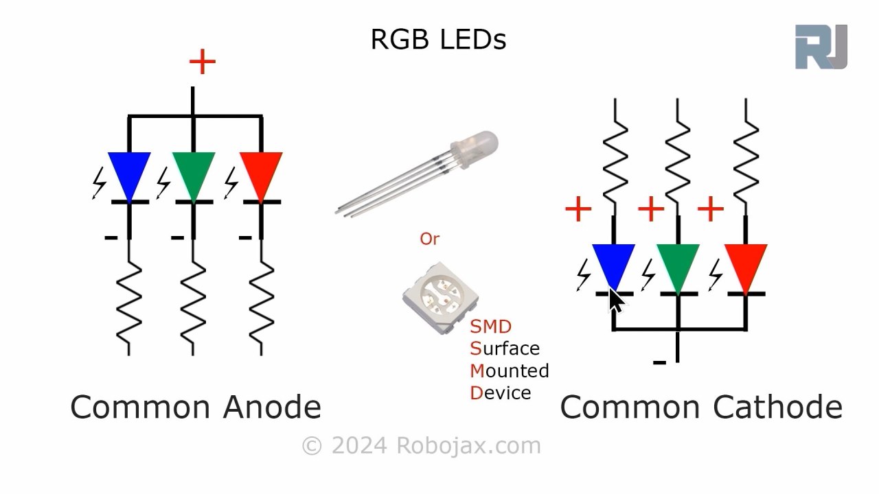
For this project, the primary components we will use are the ESP32 microcontroller and the RGB LED. The ESP32 is capable of connecting to Wi-Fi networks, allowing it to communicate with the Adafruit IO service. The RGB LED contains three individual LEDs (red, green, and blue) that can be mixed to create a wide range of colors.
The RGB LED operates on a common anode or common cathode principle, which means that the anode (positive) or cathode (negative) of the individual LEDs must be connected properly for them to work. Each color can be controlled using Pulse Width Modulation (PWM), which adjusts the brightness of each LED by varying the duty cycle.

Datasheet Details
| Manufacturer | SunFounder |
|---|---|
| Part number | RGB LED |
| Forward voltage (VF) | 2.0–3.4 V |
| Forward current (IF) | 20 mA |
| Peak wavelength (nm) | Red: 620, Green: 525, Blue: 465 |
| Package | Standard 4-pin |
| Notes / variants | Common anode or common cathode options available |
- Use 220 ohm resistors for each LED color to limit current.
- Ensure correct wiring for common anode or cathode configuration.
- Check the ESP32's power supply to avoid brownouts.
- Keep the PWM frequency within the limits for smooth color transitions.
- Ensure Wi-Fi credentials are correct to connect to the Adafruit IO service.
Wiring Instructions
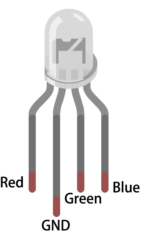
To wire the RGB LED to the ESP32, start by identifying the pins on the RGB LED. The longest pin is the common pin. For a common anode configuration, connect this pin to the positive voltage supply (3.3V). The other three pins correspond to the red, green, and blue LEDs. Connect the red pin to GPIO 27, the green pin to GPIO 26, and the blue pin to GPIO 25. Each of these connections should be made through a 220 ohm resistor to limit the current flowing through the LEDs.
Next, connect the ground (GND) of the ESP32 to the ground line of your circuit. Ensure that the wiring is secure to prevent any intermittent connections. If using a common cathode RGB LED, connect the common pin to ground instead and connect the individual color pins to the positive supply through the resistors. Double-check all connections before powering the circuit.
Code Examples & Walkthrough
In the Arduino code, we start by defining the pins for the red, green, and blue LEDs using the identifiers redPin, greenPin, and bluePin. Additionally, we define the PWM channels for each color using redChannel, greenChannel, and blueChannel. The PWM frequency is set to 5000 Hz with an 8-bit resolution.
const int redPin = 27;
const int greenPin = 26;
const int bluePin = 25;

const int redChannel = 0;
const int greenChannel = 1;
const int blueChannel = 2;
In the setup() function, we initialize the PWM channels and attach the corresponding pins. We also connect to the Wi-Fi network using the defined credentials and set up the MQTT client for communication with Adafruit IO.
void setup() {
  ledcSetup(redChannel, freq, resolution);
  ledcAttachPin(redPin, redChannel);
  // Connect to WiFi
  WiFi.begin(WLAN_SSID, WLAN_PASS);
}
The main loop checks the MQTT connection and processes incoming messages. It also prints the current RGB values to the serial monitor. The color of the LED is updated based on the values received through MQTT subscriptions.
void loop() {
  MQTT_connect();
  mqtt.processPackets(500);
  setColor();
}
For more details on the full code, please refer to the complete code loaded below the article.
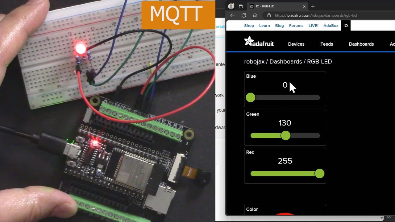
Demonstration / What to Expect
Once everything is set up and the code is uploaded, you should see the RGB LED responding to color changes made through the Adafruit IO dashboard. As you adjust the sliders for red, green, and blue, the LED should change its color accordingly. If you experience any issues, ensure that the Wi-Fi connection is stable and that the MQTT topic names match those defined in the code (in video at 17:30).
Common pitfalls include incorrect wiring, mismatched topic names, and forgetting to set the correct Wi-Fi credentials. If the LED does not light up, double-check the resistor connections and ensure that the ESP32 is powered correctly.
Video Timestamps
- 00:00 Start
- 2:23 Introduction to the project
- 4:43 What is MQTT
- 7:55 Adafruit IO setup
- 14:09 Wiring explained
- 16:07 Code explained
- 27:03 Selecting ESP32 board and COM port on Arduino IDE
- 29:12 Project demonstration
- 31:25 What is RGB LED?
- 35:26 RGB Color
Images
/***********************************************************************
 This is Arduino sketch for ESP32 to control RGB LED using MQTT service of Adafruit
 video instruction https://youtu.be/-9q1GfGsnr0
 📚⬇️ Download and resource page https://robojax.com/RJT672
 Written By Ahamd Shamshiri
 on Feb 18, 2024

  Adafruit MQTT Library ESP32 Adafruit IO SSL/TLS example


/// ref: https://www.electronicwings.com/esp32/esp32-mqtt-client
*/
// Define RGB LED pins
const int redPin = 27;
const int greenPin = 26;
const int bluePin = 25;

// Define PWM channels
const int redChannel = 0;
const int greenChannel = 1;
const int blueChannel = 2;

// Define PWM frequency and resolution
const int freq = 5000;
const int resolution = 8;
int colorR, colorG, colorB;

#include <WiFi.h>
#include "WiFiClientSecure.h"
#include "Adafruit_MQTT.h"
#include "Adafruit_MQTT_Client.h"

/************************* WiFi Access Point *********************************/


#define WLAN_SSID "Book"
#define WLAN_PASS "888-888"

/************************* Adafruit.io Setup *********************************/

#define AIO_SERVER "io.adafruit.com"

// Using port 8883 for MQTTS
#define AIO_SERVERPORT 8883

// Adafruit IO Account Configuration
// (to obtain these values, visit https://io.adafruit.com and click on Active Key)
// #define AIO_USERNAME "YOUR_ADAFRUIT_IO_USERNAME"
// #define AIO_KEY      "YOUR_ADAFRUIT_IO_KEY"

#define AIO_USERNAME "robojax"
#define AIO_KEY "aio_NBQQ75Rn7liRNcRn5uGUBMsBYmjD"

/************ Global State (you don't need to change this!) ******************/

// WiFiFlientSecure for SSL/TLS support
WiFiClientSecure client;

// Setup the MQTT client class by passing in the WiFi client and MQTT server and login details.
Adafruit_MQTT_Client mqtt(&client, AIO_SERVER, AIO_SERVERPORT, AIO_USERNAME, AIO_KEY);


// io.adafruit.com root CA
const char* adafruitio_root_ca = \
      "-----BEGIN CERTIFICATE-----\n"
      "MIIEjTCCA3WgAwIBAgIQDQd4KhM/xvmlcpbhMf/ReTANBgkqhkiG9w0BAQsFADBh\n"
      "MQswCQYDVQQGEwJVUzEVMBMGA1UEChMMRGlnaUNlcnQgSW5jMRkwFwYDVQQLExB3\n"
      "d3cuZGlnaWNlcnQuY29tMSAwHgYDVQQDExdEaWdpQ2VydCBHbG9iYWwgUm9vdCBH\n"
      "MjAeFw0xNzExMDIxMjIzMzdaFw0yNzExMDIxMjIzMzdaMGAxCzAJBgNVBAYTAlVT\n"
      "MRUwEwYDVQQKEwxEaWdpQ2VydCBJbmMxGTAXBgNVBAsTEHd3dy5kaWdpY2VydC5j\n"
      "b20xHzAdBgNVBAMTFkdlb1RydXN0IFRMUyBSU0EgQ0EgRzEwggEiMA0GCSqGSIb3\n"
      "DQEBAQUAA4IBDwAwggEKAoIBAQC+F+jsvikKy/65LWEx/TMkCDIuWegh1Ngwvm4Q\n"
      "yISgP7oU5d79eoySG3vOhC3w/3jEMuipoH1fBtp7m0tTpsYbAhch4XA7rfuD6whU\n"
      "gajeErLVxoiWMPkC/DnUvbgi74BJmdBiuGHQSd7LwsuXpTEGG9fYXcbTVN5SATYq\n"
      "DfbexbYxTMwVJWoVb6lrBEgM3gBBqiiAiy800xu1Nq07JdCIQkBsNpFtZbIZhsDS\n"
      "fzlGWP4wEmBQ3O67c+ZXkFr2DcrXBEtHam80Gp2SNhou2U5U7UesDL/xgLK6/0d7\n"
      "6TnEVMSUVJkZ8VeZr+IUIlvoLrtjLbqugb0T3OYXW+CQU0kBAgMBAAGjggFAMIIB\n"
      "PDAdBgNVHQ4EFgQUlE/UXYvkpOKmgP792PkA76O+AlcwHwYDVR0jBBgwFoAUTiJU\n"
      "IBiV5uNu5g/6+rkS7QYXjzkwDgYDVR0PAQH/BAQDAgGGMB0GA1UdJQQWMBQGCCsG\n"
      "AQUFBwMBBggrBgEFBQcDAjASBgNVHRMBAf8ECDAGAQH/AgEAMDQGCCsGAQUFBwEB\n"
      "BCgwJjAkBggrBgEFBQcwAYYYaHR0cDovL29jc3AuZGlnaWNlcnQuY29tMEIGA1Ud\n"
      "HwQ7MDkwN6A1oDOGMWh0dHA6Ly9jcmwzLmRpZ2ljZXJ0LmNvbS9EaWdpQ2VydEds\n"
      "b2JhbFJvb3RHMi5jcmwwPQYDVR0gBDYwNDAyBgRVHSAAMCowKAYIKwYBBQUHAgEW\n"
      "HGh0dHBzOi8vd3d3LmRpZ2ljZXJ0LmNvbS9DUFMwDQYJKoZIhvcNAQELBQADggEB\n"
      "AIIcBDqC6cWpyGUSXAjjAcYwsK4iiGF7KweG97i1RJz1kwZhRoo6orU1JtBYnjzB\n"
      "c4+/sXmnHJk3mlPyL1xuIAt9sMeC7+vreRIF5wFBC0MCN5sbHwhNN1JzKbifNeP5\n"
      "ozpZdQFmkCo+neBiKR6HqIA+LMTMCMMuv2khGGuPHmtDze4GmEGZtYLyF8EQpa5Y\n"
      "jPuV6k2Cr/N3XxFpT3hRpt/3usU/Zb9wfKPtWpoznZ4/44c1p9rzFcZYrWkj3A+7\n"
      "TNBJE0GmP2fhXhP1D/XVfIW/h0yCJGEiV9Glm/uGOa3DXHlmbAcxSyCRraG+ZBkA\n"
      "7h4SeM6Y8l/7MBRpPCz6l8Y=\n"
      "-----END CERTIFICATE-----\n";

/****************************** Feeds ***************************************/

// Setup a feed called 'test' for publishing and 'test2' for subscription.
// Notice MQTT paths for AIO follow the form: <username>/feeds/<feedname>
Adafruit_MQTT_Subscribe COLOR_R = Adafruit_MQTT_Subscribe(&mqtt, AIO_USERNAME "/feeds/rgb-led-color.red");
Adafruit_MQTT_Subscribe COLOR_G = Adafruit_MQTT_Subscribe(&mqtt, AIO_USERNAME "/feeds/rgb-led-color.green");
Adafruit_MQTT_Subscribe COLOR_B = Adafruit_MQTT_Subscribe(&mqtt, AIO_USERNAME "/feeds/rgb-led-color.blue");
Adafruit_MQTT_Subscribe COLOR_RGB = Adafruit_MQTT_Subscribe(&mqtt, AIO_USERNAME "/feeds/color-picker");


/*************************** Sketch Code ************************************/


void setup() {
  // Set up PWM channels
  ledcSetup(redChannel, freq, resolution);
  ledcSetup(greenChannel, freq, resolution);
  ledcSetup(blueChannel, freq, resolution);

  // Attach pins to corresponding PWM channels
  ledcAttachPin(redPin, redChannel);
  ledcAttachPin(greenPin, greenChannel);
  ledcAttachPin(bluePin, blueChannel);

  Serial.begin(115200);
  delay(10);

  Serial.println(F("Adafruit IO MQTTS (SSL/TLS) Example"));

  // Connect to WiFi access point.
  Serial.println();
  Serial.println();
  Serial.print("Connecting to ");
  Serial.println(WLAN_SSID);

  delay(1000);

  WiFi.begin(WLAN_SSID, WLAN_PASS);
  delay(2000);

  while (WiFi.status() != WL_CONNECTED) {
    delay(500);
    Serial.print(".");
  }
  Serial.println();

  Serial.println("WiFi connected");
  Serial.println("IP address: ");
  Serial.println(WiFi.localIP());

  // Set Adafruit IO's root CA
  client.setCACert(adafruitio_root_ca);

  // register callback for feed
  COLOR_R.setCallback(color_R_Callback);
  // Setup MQTT subscription for time feed.
  mqtt.subscribe(&COLOR_R);

    // register callback for feed
  COLOR_G.setCallback(color_G_Callback);
  // Setup MQTT subscription for time feed.
  mqtt.subscribe(&COLOR_G);

    // register callback for feed
  COLOR_B.setCallback(color_B_Callback);
  // Setup MQTT subscription for time feed.
  mqtt.subscribe(&COLOR_B);

    // register callback for feed
  COLOR_RGB.setCallback(color_RGB_Callback);
  // Setup MQTT subscription for time feed.
  mqtt.subscribe(&COLOR_RGB);


}

// uint32_t x=0;


void loop() {

  // Ensure the connection to the MQTT server is alive (this will make the first
  // connection and automatically reconnect when disconnected).  See the MQTT_connect
  // function definition further below.
  MQTT_connect();

  Serial.print("R: ");
  Serial.print (colorR);
  Serial.print(" G: ");
  Serial.print (colorG);
  Serial.print(" B: ");
  Serial.println(colorB);

  // wait 0.5 seconds for subscription messages
  mqtt.processPackets(500);
  setColor();

  // wait a couple seconds to avoid rate limit
  //delay(2000);
}

void color_R_Callback(char* message, uint16_t len) {
  char messageBuffer[40];
  //snprintf(messageBuffer, sizeof(messageBuffer), "Color status is :: %s, len :: %u", message, len);
  //Serial.println(messageBuffer);
  Serial.println(message);
  String inString = message;//sotre the message to String

  colorR  =  inString.toInt();//convert the message to Integer
  if(colorR >255 || colorR < 0)
  {
    colorR = 0;
  }

}

void color_G_Callback(char* message, uint16_t len) {
  char messageBuffer[40];
  //snprintf(messageBuffer, sizeof(messageBuffer), "Color status is :: %s, len :: %u", message, len);
  //Serial.println(messageBuffer);
  Serial.println(message);
  String inString = message;//sotre the message to String

  colorG  =  inString.toInt();//convert the message to Integer
  if(colorG >255 || colorG < 0)
  {
    colorG = 0;
  }

}

void color_B_Callback(char* message, uint16_t len) {
  char messageBuffer[40];
  //snprintf(messageBuffer, sizeof(messageBuffer), "Color status is :: %s, len :: %u", message, len);
  //Serial.println(messageBuffer);
  Serial.println(message);
  String inString = message;//sotre the message to String

  colorB  =  inString.toInt();//convert the message to Integer
  if(colorB >255 || colorB < 0)
  {
    colorB = 0;
  }

}

void color_RGB_Callback(char* message, uint16_t len) {
  char messageBuffer[40];
  //snprintf(messageBuffer, sizeof(messageBuffer), "Color status is :: %s, len :: %u", message, len);
  //Serial.println(messageBuffer);
  Serial.println(message);
  String newColor = String( message);//
  if(newColor.length() == 7)
  {

    String theColorR = newColor.substring(1, 3);//extract B2 from  #B2a48d for example
    String theColorG = newColor.substring(3, 5);//extract a4 from  #B2a48d for example
    String theColorB = newColor.substring(5, 7);//extract 8d from  #B2a48d for example

    colorR = StrToHex(theColorR.c_str());//convert String to HEX for R
    colorG = StrToHex(theColorG.c_str());//convert String to HEX for G
    colorB = StrToHex(theColorB.c_str());//convert String to HEX for B


  }


}

//from https://stackoverflow.com/questions/44683071/convert-string-as-hex-to-hexadecimal
uint64_t StrToHex(const char* str)
{
  return (uint64_t) strtoull(str, 0, 16);
}

void setColor() {
  // For common-anode RGB LEDs, use 255 minus the color value
  ledcWrite(redChannel, colorR);
  ledcWrite(greenChannel, colorG);
  ledcWrite(blueChannel, colorB);
}


// Function to connect and reconnect as necessary to the MQTT server.
// Should be called in the loop function and it will take care if connecting.
void MQTT_connect() {
  int8_t ret;
  // Stop if already connected.
  if (mqtt.connected()) {
    return;
  }
  Serial.print("Connecting to MQTT... ");
  uint8_t retries = 3;
  while ((ret = mqtt.connect()) != 0) {  // connect will return 0 for connected
    Serial.println(mqtt.connectErrorString(ret));
    Serial.println("Retrying MQTT connection in 5 seconds...");
    mqtt.disconnect();
    delay(5000);  // wait 5 seconds
    retries--;
    if (retries == 0) {
      // basically die and wait for WDT to reset me
      while (1)
        ;
    }
  }
  Serial.println("MQTT Connected!");
}
Common Course Links
Common Course Files
Resources & references
No resources yet.
Files📁
No files available.