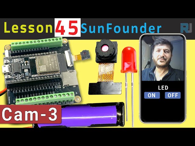
Tutorial ESP32 45/55 - Servidor de Streaming Personalizado com controle de LED CAM-3 l Kit de Aprendizado ESP32 da SunFounder
Neste tutorial, vamos explorar como configurar um servidor de streaming personalizado usando a placa de extensão ESP32 da SunFounder. O projeto permite que você transmita vídeo ao vivo para seu navegador enquanto controla um LED diretamente da interface. Essa combinação de recursos proporciona uma experiência de aprendizado prático com IoT e tecnologias da web.
Usaremos as capacidades de Wi-Fi integradas do ESP32 para criar um servidor web que transmite vídeo e controla comandos de LED. O projeto envolve codificação, fiação e compreensão de como os componentes interagem. Se você quiser uma compreensão mais clara da configuração, não deixe de conferir o vídeo em (no vídeo em 00:00).
Hardware Explicado
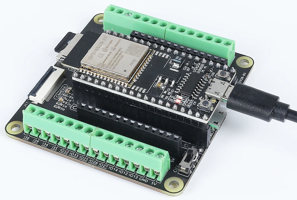
Os principais componentes deste projeto incluem o microcontrolador ESP32, um módulo de câmera, um LED e um resistor. O ESP32 é um microcontrolador versátil com Wi-Fi e Bluetooth integrados, tornando-o perfeito para aplicações de IoT. O módulo de câmera nos permite capturar vídeo, enquanto o LED fornece um dispositivo de saída simples para controle.
O LED está conectado através de um resistor para limitar a corrente, prevenindo danos tanto ao LED quanto ao microcontrolador. Esta configuração nos permitirá ligar e desligar o LED através da nossa interface web, demonstrando as capacidades do ESP32 em lidar com entradas e saídas em uma rede.
Detalhes da Ficha Técnica
| Fabricante | Espressif |
|---|---|
| Número da peça | ESP32-WROOM-32 |
| Tensão de lógica/IO | 3,3 V |
| Tensão de alimentação | 3,0-3,6 V |
| Corrente de saída (por canal) | 12 mA |
| Corrente de pico (por canal) | 40 mA |
| Orientações sobre frequência PWM | 1 kHz |
| Limiar de lógica de entrada | 0,2 V (baixo) / 0,8 V (alto) |
| Queda de tensão / RDS(on)/ saturação | 0,2 V (típ.) |
| Limites térmicos | Temperatura máxima de junção: 125 °C |
| Pacote | QFN48 |
| Notas / variantes | Disponível em várias configurações |
- Certifique-se de que o ESP32 esteja alimentado com uma fonte regulada de 3,3 V.
- Use um resistor limitador de corrente (220 Ohm) com o LED para prevenir danos.
- Mantenha conexões adequadas para evitar entradas flutuantes.
- Verifique se as credenciais do Wi-Fi estão corretas e são sensíveis a maiúsculas e minúsculas.
- Use uma fonte de energia estável para desempenho consistente.
- Considere a dissipação de calor em espaços fechados.
Instruções de Fiação

Para conectar o ESP32 e o LED, comece ligando o pino mais longo do LED a um pino GPIO adequado, neste caso, usaremos o pino 14. O pino mais curto deve ser conectado à linha de terra na sua placa de ensaio. Em seguida, coloque um resistor de 220 Ohms em série com o LED, conectando uma extremidade ao pino GPIO (pino 14) e a outra extremidade à terra. Certifique-se de que o ESP32 esteja alimentado corretamente, seja através da porta micro USB ou com uma bateria de lítio 18650.
Para o módulo da câmera, certifique-se de conectar os pinos necessários de acordo com o modelo da câmera que você está usando, pois a fiação pode variar um pouco. O ESP32 irá gerenciar o fluxo de vídeo através de suas capacidades integradas, e o controle do LED será feito por meio da interface web que iremos configurar no código.
Exemplos de Código e Passo a Passo
O programa começa incluindo as bibliotecas necessárias e definindo as credenciais do Wi-Fi. Você precisará substituirssidepasswordcom suas credenciais Wi-Fi reais para conectar o ESP32 à sua rede.
const char* ssid = "SSID";
const char* password = "PASSWORD";
Em seguida, definimos o pino do LED e configuramos as configurações da câmera. O pino usado para o LED é definido comoLED_PIN, que será usado mais tarde no código para controlar o estado do LED.
#define LED_PIN    14
pinMode(LED_PIN, OUTPUT);
No traduçao para o manipulador de solicitações do controle de LED, verificamos o comando recebido da interface web. Dependendo se o comando é "on" ou "off", usamosdigitalWrite(LED_PIN, 1);para acender o LED edigitalWrite(LED_PIN, 0);desligá-lo.
if(!strcmp(variable, "on")) {
  Serial.println("ON");
  digitalWrite(LED_PIN, 1);
}
else if(!strcmp(variable, "off")) {
  Serial.println("OFF");
  digitalWrite(LED_PIN, 0);
}
Essa lógica permite que a interface web se comunique efetivamente com o ESP32, possibilitando o controle em tempo real do LED com base nas interações do usuário. O código completo está carregado abaixo do artigo para uma exploração adicional.
Demonstração / O que Esperar
Uma vez que tudo esteja configurado e o código carregado, você deve conseguir acessar o endereço IP do ESP32 no seu navegador. O vídeo em streaming aparecerá, e você poderá controlar o LED usando os botões na interface. Clicar em "ON" acenderá o LED, enquanto "OFF" o apagará. Certifique-se de que o ESP32 e o seu computador estejam conectados à mesma rede para garantir o funcionamento adequado (no vídeo às 12:30).
Marcação de Tempo do Vídeo
- 00:00 Início
- 1:51 Introdução ao projeto
- 2:31 Página de documentação
- 3:33 Fiação Explicada
- 5:08 Código Arduino explicado
- 13:28 Selecionando a placa ESP32 e a porta COM no Arduino IDE
- 15:10 Demonstração
Imagens
/*
 * A permissão é concedida, gratuitamente, a qualquer pessoa que obtenha uma cópia deste software e dos arquivos de documentação associados. O aviso de copyright acima e este aviso de permissão devem ser incluídos em todas as cópias ou porções substanciais do Software.
 */
#include "esp_camera.h"
#include <WiFi.h>
#include "esp_timer.h"
#include "img_converters.h"
#include "Arduino.h"
#include "fb_gfx.h"
#include "soc/soc.h" // desabilitar problemas de queda de tensão
#include "soc/rtc_cntl_reg.h" // desabilitar problemas de queda de tensão
#include "esp_http_server.h"

 // Substitua as próximas variáveis pela combinação do seu SSID/senha.
const char* ssid = "SSID";
const char* password = "PASSWORD";

#define PART_BOUNDARY "123456789000000000000987654321"

#define CAMERA_MODEL_AI_THINKER
 // #define CAMERA_MODEL_M5STACK_PSRAM
 // #define CAMERA_MODEL_M5STACK_COM_SANS_PSRAM
 // #define MODEL_CAMERA_M5STACK_PSRAM_B
 // #define CAMERA_MODEL_WROVER_KIT

#if defined(CAMERA_MODEL_WROVER_KIT)
  #define PWDN_GPIO_NUM    -1
  #define RESET_GPIO_NUM   -1
  #define XCLK_GPIO_NUM    21
  #define SIOD_GPIO_NUM    26
  #define SIOC_GPIO_NUM    27

  #define Y9_GPIO_NUM      35
  #define Y8_GPIO_NUM      34
  #define Y7_GPIO_NUM      39
  #define Y6_GPIO_NUM      36
  #define Y5_GPIO_NUM      19
  #define Y4_GPIO_NUM      18
  #define Y3_GPIO_NUM       5
  #define Y2_GPIO_NUM       4
  #define VSYNC_GPIO_NUM   25
  #define HREF_GPIO_NUM    23
  #define PCLK_GPIO_NUM    22

#elif defined(CAMERA_MODEL_M5STACK_PSRAM)
  #define PWDN_GPIO_NUM     -1
  #define RESET_GPIO_NUM    15
  #define XCLK_GPIO_NUM     27
  #define SIOD_GPIO_NUM     25
  #define SIOC_GPIO_NUM     23

  #define Y9_GPIO_NUM       19
  #define Y8_GPIO_NUM       36
  #define Y7_GPIO_NUM       18
  #define Y6_GPIO_NUM       39
  #define Y5_GPIO_NUM        5
  #define Y4_GPIO_NUM       34
  #define Y3_GPIO_NUM       35
  #define Y2_GPIO_NUM       32
  #define VSYNC_GPIO_NUM    22
  #define HREF_GPIO_NUM     26
  #define PCLK_GPIO_NUM     21

#elif defined(CAMERA_MODEL_M5STACK_WITHOUT_PSRAM)
  #define PWDN_GPIO_NUM     -1
  #define RESET_GPIO_NUM    15
  #define XCLK_GPIO_NUM     27
  #define SIOD_GPIO_NUM     25
  #define SIOC_GPIO_NUM     23

  #define Y9_GPIO_NUM       19
  #define Y8_GPIO_NUM       36
  #define Y7_GPIO_NUM       18
  #define Y6_GPIO_NUM       39
  #define Y5_GPIO_NUM        5
  #define Y4_GPIO_NUM       34
  #define Y3_GPIO_NUM       35
  #define Y2_GPIO_NUM       17
  #define VSYNC_GPIO_NUM    22
  #define HREF_GPIO_NUM     26
  #define PCLK_GPIO_NUM     21

#elif defined(CAMERA_MODEL_AI_THINKER)
  #define PWDN_GPIO_NUM     32
  #define RESET_GPIO_NUM    33
  #define XCLK_GPIO_NUM      0
  #define SIOD_GPIO_NUM     26
  #define SIOC_GPIO_NUM     27

  #define Y9_GPIO_NUM       35
  #define Y8_GPIO_NUM       34
  #define Y7_GPIO_NUM       39
  #define Y6_GPIO_NUM       36
  #define Y5_GPIO_NUM       21
  #define Y4_GPIO_NUM       19
  #define Y3_GPIO_NUM       18
  #define Y2_GPIO_NUM        5
  #define VSYNC_GPIO_NUM    25
  #define HREF_GPIO_NUM     23
  #define PCLK_GPIO_NUM     22

#elif defined(CAMERA_MODEL_M5STACK_PSRAM_B)
  #define PWDN_GPIO_NUM     -1
  #define RESET_GPIO_NUM    15
  #define XCLK_GPIO_NUM     27
  #define SIOD_GPIO_NUM     22
  #define SIOC_GPIO_NUM     23

  #define Y9_GPIO_NUM       19
  #define Y8_GPIO_NUM       36
  #define Y7_GPIO_NUM       18
  #define Y6_GPIO_NUM       39
  #define Y5_GPIO_NUM        5
  #define Y4_GPIO_NUM       34
  #define Y3_GPIO_NUM       35
  #define Y2_GPIO_NUM       32
  #define VSYNC_GPIO_NUM    25
  #define HREF_GPIO_NUM     26
  #define PCLK_GPIO_NUM     21

#else
  #error "Camera model not selected"
#endif

#define LED_PIN    14

static const char* _STREAM_CONTENT_TYPE = "multipart/x-mixed-replace;boundary=" PART_BOUNDARY;
static const char* _STREAM_BOUNDARY = "\r\n--" PART_BOUNDARY "\r\n";
static const char* _STREAM_PART = "Content-Type: image/jpeg\r\nContent-Length: %u\r\n\r\n";

httpd_handle_t camera_httpd = NULL;
httpd_handle_t stream_httpd = NULL;

static const char PROGMEM INDEX_HTML[] = R"rawliteral(
<html>
  <head>
    <title>ESP32-CAM Robot</title>
    <meta name="viewport" content="width=device-width, initial-scale=1">
    <style>
      body { font-family: Arial; text-align: center; margin:0px auto; padding-top: 30px;}
      table { margin-left: auto; margin-right: auto; }
      td { padding: 8 px; }
      .button {
        background-color: #2f4468;
        border: none;
        color: white;
        padding: 10px 20px;
        text-align: center;
        text-decoration: none;
        display: inline-block;
        font-size: 18px;
        margin: 6px 3px;
        cursor: pointer;
        -webkit-touch-callout: none;
        -webkit-user-select: none;
        -khtml-user-select: none;
        -moz-user-select: none;
        -ms-user-select: none;
        user-select: none;
        -webkit-tap-highlight-color: rgba(0,0,0,0);
      }
      img {  width: auto ;
        max-width: 100% ;
        height: auto ;
        transform: rotate(180deg);
      }
    </style>
  </head>
  <body>
    <h1>ESP32 CAMERA</h1>
    <img src="" id="photo" >
    <table>
      <tr><td align="center"><button class="button" onmousedown="toggleCheckbox('on');" ontouchstart="toggleCheckbox('on');onmouseup="toggleCheckbox('on');" ontouchend="toggleCheckbox('on');">ON</button></td>
      <td align="center"><button class="button" onmousedown="toggleCheckbox('off');" ontouchstart="toggleCheckbox('off');onmouseup="toggleCheckbox('off');" ontouchend="toggleCheckbox('off');">OFF</button></td></tr>
    </table>
   <script>
   function toggleCheckbox(x) {
     var xhr = new XMLHttpRequest();
     xhr.open("GET", "/action?go=" + x, true);
     xhr.send();
   }
   window.onload = document.getElementById("photo").src = window.location.href.slice(0, -1) + ":81/stream";
  </script>
  </body>
</html>
)rawliteral";

static esp_err_t index_handler(httpd_req_t *req){
  httpd_resp_set_type(req, "text/html");
  return httpd_resp_send(req, (const char *)INDEX_HTML, strlen(INDEX_HTML));
}

static esp_err_t stream_handler(httpd_req_t *req){
  camera_fb_t * fb = NULL;
  esp_err_t res = ESP_OK;
  size_t _jpg_buf_len = 0;
  uint8_t * _jpg_buf = NULL;
  char * part_buf[64];

  res = httpd_resp_set_type(req, _STREAM_CONTENT_TYPE);
  if(res != ESP_OK){
    return res;
  }

  while(true){
    fb = esp_camera_fb_get();
    if (!fb) {
      Serial.println("Camera capture failed");
      res = ESP_FAIL;
    } else {
      if(fb->width > 400){
        if(fb->format != PIXFORMAT_JPEG){
          bool jpeg_converted = frame2jpg(fb, 80, &_jpg_buf, &_jpg_buf_len);
          esp_camera_fb_return(fb);
          fb = NULL;
          if(!jpeg_converted){
            Serial.println("JPEG compression failed");
            res = ESP_FAIL;
          }
        } else {
          _jpg_buf_len = fb->len;
          _jpg_buf = fb->buf;
        }
      }
    }
    if(res == ESP_OK){
      size_t hlen = snprintf((char *)part_buf, 64, _STREAM_PART, _jpg_buf_len);
      res = httpd_resp_send_chunk(req, (const char *)part_buf, hlen);
    }
    if(res == ESP_OK){
      res = httpd_resp_send_chunk(req, (const char *)_jpg_buf, _jpg_buf_len);
    }
    if(res == ESP_OK){
      res = httpd_resp_send_chunk(req, _STREAM_BOUNDARY, strlen(_STREAM_BOUNDARY));
    }
    if(fb){
      esp_camera_fb_return(fb);
      fb = NULL;
      _jpg_buf = NULL;
    } else if(_jpg_buf){
      free(_jpg_buf);
      _jpg_buf = NULL;
    }
    if(res != ESP_OK){
      break;
    }
 // Serial.printf("MJPG: %uB\n",(uint32_t)(_jpg_buf_len));
  }
  return res;
}

static esp_err_t cmd_handler(httpd_req_t *req){
  char*  buf;
  size_t buf_len;
  char variable[32] = {0,};

  buf_len = httpd_req_get_url_query_len(req) + 1;
  if (buf_len > 1) {
    buf = (char*)malloc(buf_len);
    if(!buf){
      httpd_resp_send_500(req);
      return ESP_FAIL;
    }
    if (httpd_req_get_url_query_str(req, buf, buf_len) == ESP_OK) {
      if (httpd_query_key_value(buf, "go", variable, sizeof(variable)) == ESP_OK) {
      } else {
        free(buf);
        httpd_resp_send_404(req);
        return ESP_FAIL;
      }
    } else {
      free(buf);
      httpd_resp_send_404(req);
      return ESP_FAIL;
    }
    free(buf);
  } else {
    httpd_resp_send_404(req);
    return ESP_FAIL;
  }

  sensor_t * s = esp_camera_sensor_get();
  int res = 0;

  if(!strcmp(variable, "on")) {
    Serial.println("ON");
    digitalWrite(LED_PIN, 1);
  }
  else if(!strcmp(variable, "off")) {
    Serial.println("OFF");
    digitalWrite(LED_PIN, 0);
  }
  else {
    res = -1;
  }

  if(res){
    return httpd_resp_send_500(req);
  }

  httpd_resp_set_hdr(req, "Access-Control-Allow-Origin", "*");
  return httpd_resp_send(req, NULL, 0);
}

void startCameraServer(){
  httpd_config_t config = HTTPD_DEFAULT_CONFIG();
  config.server_port = 80;
  httpd_uri_t index_uri = {
    .uri       = "/",
    .method    = HTTP_GET,
    .handler   = index_handler,
    .user_ctx  = NULL
  };

  httpd_uri_t cmd_uri = {
    .uri       = "/action",
    .method    = HTTP_GET,
    .handler   = cmd_handler,
    .user_ctx  = NULL
  };
  httpd_uri_t stream_uri = {
    .uri       = "/stream",
    .method    = HTTP_GET,
    .handler   = stream_handler,
    .user_ctx  = NULL
  };
  if (httpd_start(&camera_httpd, &config) == ESP_OK) {
    httpd_register_uri_handler(camera_httpd, &index_uri);
    httpd_register_uri_handler(camera_httpd, &cmd_uri);
  }
  config.server_port += 1;
  config.ctrl_port += 1;
  if (httpd_start(&stream_httpd, &config) == ESP_OK) {
    httpd_register_uri_handler(stream_httpd, &stream_uri);
  }
}

void setup() {
  WRITE_PERI_REG(RTC_CNTL_BROWN_OUT_REG, 0); // desativar o detector de brownout

  pinMode(LED_PIN, OUTPUT);

  Serial.begin(115200);
  Serial.setDebugOutput(false);

  camera_config_t config;
  config.ledc_channel = LEDC_CHANNEL_0;
  config.ledc_timer = LEDC_TIMER_0;
  config.pin_d0 = Y2_GPIO_NUM;
  config.pin_d1 = Y3_GPIO_NUM;
  config.pin_d2 = Y4_GPIO_NUM;
  config.pin_d3 = Y5_GPIO_NUM;
  config.pin_d4 = Y6_GPIO_NUM;
  config.pin_d5 = Y7_GPIO_NUM;
  config.pin_d6 = Y8_GPIO_NUM;
  config.pin_d7 = Y9_GPIO_NUM;
  config.pin_xclk = XCLK_GPIO_NUM;
  config.pin_pclk = PCLK_GPIO_NUM;
  config.pin_vsync = VSYNC_GPIO_NUM;
  config.pin_href = HREF_GPIO_NUM;
  config.pin_sscb_sda = SIOD_GPIO_NUM;
  config.pin_sscb_scl = SIOC_GPIO_NUM;
  config.pin_pwdn = PWDN_GPIO_NUM;
  config.pin_reset = RESET_GPIO_NUM;
  config.xclk_freq_hz = 20000000;
  config.pixel_format = PIXFORMAT_JPEG;

  if(psramFound()){
    config.frame_size = FRAMESIZE_VGA;
    config.jpeg_quality = 10;
    config.fb_count = 2;
  } else {
    config.frame_size = FRAMESIZE_SVGA;
    config.jpeg_quality = 12;
    config.fb_count = 1;
  }

 // Inicialização da câmera
  esp_err_t err = esp_camera_init(&config);
  if (err != ESP_OK) {
    Serial.printf("Camera init failed with error 0x%x", err);
    return;
  }
 // Conexão Wi-Fi
  WiFi.begin(ssid, password);
  while (WiFi.status() != WL_CONNECTED) {
    delay(500);
    Serial.print(".");
  }
  Serial.println("");
  Serial.println("WiFi connected");

  Serial.print("Camera Stream Ready! Go to: http: // ");
  Serial.println(WiFi.localIP());

 // Iniciar o servidor web de streaming
  startCameraServer();
}

void loop() {

}
Common Course Links
Common Course Files
Recursos e referências
-
Documentação
Arquivos📁
Nenhum arquivo disponível.