Tutorial ESP32 45/55 - Servidor de Streaming Personalizado con control de LED CAM-3 l Kit de Aprendizaje ESP32 de SunFounder
En este tutorial, exploraremos cómo configurar un servidor de streaming personalizado utilizando la placa de expansión ESP32 de SunFounder. El proyecto te permite transmitir video en vivo a tu navegador mientras también controlas un LED directamente desde la interfaz. Esta combinación de funciones permite una experiencia de aprendizaje práctica con tecnologías IoT y web.
Usaremos las capacidades Wi-Fi integradas del ESP32 para crear un servidor web que transmita video y maneje comandos de control de LED. El proyecto implica codificación, cableado y comprensión de cómo interactúan los componentes. Si quieres una comprensión más clara de la configuración, asegúrate de ver el video en (en el video a :00).
Hardware Explicado
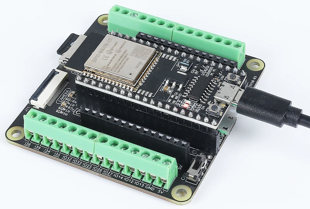
Los componentes principales de este proyecto incluyen el microcontrolador ESP32, un módulo de cámara, un LED y una resistencia. El ESP32 es un microcontrolador versátil con Wi-Fi y Bluetooth integrados, lo que lo hace perfecto para aplicaciones de IoT. El módulo de cámara nos permite capturar video, mientras que el LED proporciona un dispositivo de salida simple para el control.
El LED está conectado a través de una resistencia para limitar la corriente, evitando daños tanto al LED como al microcontrolador. Esta configuración nos permitirá encender y apagar el LED a través de nuestra interfaz web, mostrando las capacidades del ESP32 en el manejo de entradas y salidas a través de una red.
Detalles de la hoja de datos
| Fabricante | Espressif |
|---|---|
| Número de parte | ESP32-WROOM-32 |
| Voltaje de lógica/IO | 3.3 V |
| Tensión de suministro | 3.0-3.6 V |
| Corriente de salida (por canal) | 12 mA |
| Corriente pico (por canal) | 40 mA |
| Guía de frecuencia PWM | 1 kHz |
| Umbrales de lógica de entrada | 0.2 V (bajo) / 0.8 V (alto) |
| Caída de tensión / RDS(on)/ saturación | 0.2 V (típ.) |
| Límites térmicos | Temperatura máxima de unión: 125 °C |
| Paquete | QFN48 |
| Notas / variantes | Disponible en varias configuraciones |
- Asegúrate de que el ESP32 esté alimentado con una fuente regulada de 3.3 V.
- Utiliza una resistencia limitadora de corriente (220 Ohmios) con el LED para prevenir daños.
- Mantén las conexiones adecuadas para evitar entradas flotantes.
- Verifique que las credenciales de Wi-Fi sean correctas y respeten las mayúsculas.
- Utiliza una fuente de energía estable para un rendimiento constante.
- Considera la disipación de calor en espacios cerrados.
Instrucciones de cableado

Para cablear el ESP32 y el LED, comienza conectando el pin más largo del LED a un pin GPIO adecuado; en este caso, usaremos el pin 14. El pin más corto debe conectarse a la línea de tierra en tu placa de pruebas. A continuación, coloca una resistencia de 220 Ohmios en serie con el LED, conectando un extremo al pin GPIO (pin 14) y el otro extremo a tierra. Asegúrate de que el ESP32 esté alimentado correctamente, ya sea a través del puerto micro USB o con una batería de litio 18650.
Para el módulo de la cámara, asegúrate de conectar los pines necesarios según el modelo de cámara que estés utilizando, ya que el cableado puede variar ligeramente. El ESP32 manejará el flujo de video a través de sus capacidades integradas, y el control de LED se gestionará a través de la interfaz web que configuraremos en el código.
Ejemplos de código y guía paso a paso
El programa comienza incluyendo las bibliotecas necesarias y definiendo las credenciales de Wi-Fi. Necesitarás reemplazarssidypasswordcon tus credenciales de Wi-Fi actuales para conectar el ESP32 a tu red.
const char* ssid = "SSID";
const char* password = "PASSWORD";
A continuación, definimos el pin del LED y configuramos las configuraciones de la cámara. El pin utilizado para el LED se define comoLED_PIN, que se utilizará más adelante en el código para controlar el estado del LED.
#define LED_PIN    14
pinMode(LED_PIN, OUTPUT);
En el manejador de solicitudes para el control de LED, verificamos el comando recibido de la interfaz web. Dependiendo de si el comando es "on" u "off", usamosdigitalWrite(LED_PIN, 1);encender el LED ydigitalWrite(LED_PIN, 0);para apagarlo.
if(!strcmp(variable, "on")) {
  Serial.println("ON");
  digitalWrite(LED_PIN, 1);
}
else if(!strcmp(variable, "off")) {
  Serial.println("OFF");
  digitalWrite(LED_PIN, 0);
}
Esta lógica permite que la interfaz web se comunique de manera efectiva con el ESP32, lo que permite el control en tiempo real del LED basado en las interacciones del usuario. El código completo se carga a continuación del artículo para una exploración adicional.
Demostración / Qué esperar
Una vez que todo esté configurado y el código esté cargado, deberías poder acceder a la dirección IP del ESP32 en tu navegador web. El vídeo en streaming aparecerá y podrás controlar el LED utilizando los botones en la interfaz. Hacer clic en "ON" encenderá el LED, mientras que "OFF" lo apagará. Asegúrate de que el ESP32 y tu computadora estén conectados a la misma red para garantizar un funcionamiento adecuado (en el vídeo a las 12:30).
Marcas de tiempo del video
- 00:00 Comienzo
- 1:51 Introducción al proyecto
- 2:31 Página de documentación
- 3:33 Explicación del cableado
- 5:08 Código de Arduino explicado
- 13:28 Seleccionando la placa ESP32 y el puerto COM en el IDE de Arduino
- 15:10 Demostración
Imágenes
/*
 * Se concede por la presente permiso, de forma gratuita, a cualquier persona que obtenga una copia de este software y los archivos de documentación asociados. El aviso de copyright anterior y este aviso de permiso se incluirán en todas las copias o partes sustanciales del Software.
 */
#include "esp_camera.h"
#include <WiFi.h>
#include "esp_timer.h"
#include "img_converters.h"
#include "Arduino.h"
#include "fb_gfx.h"
#include "soc/soc.h" // desactivar problemas de apagones
#include "soc/rtc_cntl_reg.h" // desactivar problemas de apagones
#include "esp_http_server.h"

 // Reemplace las siguientes variables con su combinación de SSID/contraseña.
const char* ssid = "SSID";
const char* password = "PASSWORD";

#define PART_BOUNDARY "123456789000000000000987654321"

#define CAMERA_MODEL_AI_THINKER
 // #define CAMERA_MODEL_M5STACK_PSRAM
 // #define CAMERA_MODEL_M5STACK_SIN_PSRAM
 // #define CAMERA_MODEL_M5STACK_PSRAM_B
 // #define CAMERA_MODEL_WROVER_KIT

#if defined(CAMERA_MODEL_WROVER_KIT)
  #define PWDN_GPIO_NUM    -1
  #define RESET_GPIO_NUM   -1
  #define XCLK_GPIO_NUM    21
  #define SIOD_GPIO_NUM    26
  #define SIOC_GPIO_NUM    27

  #define Y9_GPIO_NUM      35
  #define Y8_GPIO_NUM      34
  #define Y7_GPIO_NUM      39
  #define Y6_GPIO_NUM      36
  #define Y5_GPIO_NUM      19
  #define Y4_GPIO_NUM      18
  #define Y3_GPIO_NUM       5
  #define Y2_GPIO_NUM       4
  #define VSYNC_GPIO_NUM   25
  #define HREF_GPIO_NUM    23
  #define PCLK_GPIO_NUM    22

#elif defined(CAMERA_MODEL_M5STACK_PSRAM)
  #define PWDN_GPIO_NUM     -1
  #define RESET_GPIO_NUM    15
  #define XCLK_GPIO_NUM     27
  #define SIOD_GPIO_NUM     25
  #define SIOC_GPIO_NUM     23

  #define Y9_GPIO_NUM       19
  #define Y8_GPIO_NUM       36
  #define Y7_GPIO_NUM       18
  #define Y6_GPIO_NUM       39
  #define Y5_GPIO_NUM        5
  #define Y4_GPIO_NUM       34
  #define Y3_GPIO_NUM       35
  #define Y2_GPIO_NUM       32
  #define VSYNC_GPIO_NUM    22
  #define HREF_GPIO_NUM     26
  #define PCLK_GPIO_NUM     21

#elif defined(CAMERA_MODEL_M5STACK_WITHOUT_PSRAM)
  #define PWDN_GPIO_NUM     -1
  #define RESET_GPIO_NUM    15
  #define XCLK_GPIO_NUM     27
  #define SIOD_GPIO_NUM     25
  #define SIOC_GPIO_NUM     23

  #define Y9_GPIO_NUM       19
  #define Y8_GPIO_NUM       36
  #define Y7_GPIO_NUM       18
  #define Y6_GPIO_NUM       39
  #define Y5_GPIO_NUM        5
  #define Y4_GPIO_NUM       34
  #define Y3_GPIO_NUM       35
  #define Y2_GPIO_NUM       17
  #define VSYNC_GPIO_NUM    22
  #define HREF_GPIO_NUM     26
  #define PCLK_GPIO_NUM     21

#elif defined(CAMERA_MODEL_AI_THINKER)
  #define PWDN_GPIO_NUM     32
  #define RESET_GPIO_NUM    33
  #define XCLK_GPIO_NUM      0
  #define SIOD_GPIO_NUM     26
  #define SIOC_GPIO_NUM     27

  #define Y9_GPIO_NUM       35
  #define Y8_GPIO_NUM       34
  #define Y7_GPIO_NUM       39
  #define Y6_GPIO_NUM       36
  #define Y5_GPIO_NUM       21
  #define Y4_GPIO_NUM       19
  #define Y3_GPIO_NUM       18
  #define Y2_GPIO_NUM        5
  #define VSYNC_GPIO_NUM    25
  #define HREF_GPIO_NUM     23
  #define PCLK_GPIO_NUM     22

#elif defined(CAMERA_MODEL_M5STACK_PSRAM_B)
  #define PWDN_GPIO_NUM     -1
  #define RESET_GPIO_NUM    15
  #define XCLK_GPIO_NUM     27
  #define SIOD_GPIO_NUM     22
  #define SIOC_GPIO_NUM     23

  #define Y9_GPIO_NUM       19
  #define Y8_GPIO_NUM       36
  #define Y7_GPIO_NUM       18
  #define Y6_GPIO_NUM       39
  #define Y5_GPIO_NUM        5
  #define Y4_GPIO_NUM       34
  #define Y3_GPIO_NUM       35
  #define Y2_GPIO_NUM       32
  #define VSYNC_GPIO_NUM    25
  #define HREF_GPIO_NUM     26
  #define PCLK_GPIO_NUM     21

#else
  #error "Camera model not selected"
#endif

#define LED_PIN    14

static const char* _STREAM_CONTENT_TYPE = "multipart/x-mixed-replace;boundary=" PART_BOUNDARY;
static const char* _STREAM_BOUNDARY = "\r\n--" PART_BOUNDARY "\r\n";
static const char* _STREAM_PART = "Content-Type: image/jpeg\r\nContent-Length: %u\r\n\r\n";

httpd_handle_t camera_httpd = NULL;
httpd_handle_t stream_httpd = NULL;

static const char PROGMEM INDEX_HTML[] = R"rawliteral(
<html>
  <head>
    <title>ESP32-CAM Robot</title>
    <meta name="viewport" content="width=device-width, initial-scale=1">
    <style>
      body { font-family: Arial; text-align: center; margin:0px auto; padding-top: 30px;}
      table { margin-left: auto; margin-right: auto; }
      td { padding: 8 px; }
      .button {
        background-color: #2f4468;
        border: none;
        color: white;
        padding: 10px 20px;
        text-align: center;
        text-decoration: none;
        display: inline-block;
        font-size: 18px;
        margin: 6px 3px;
        cursor: pointer;
        -webkit-touch-callout: none;
        -webkit-user-select: none;
        -khtml-user-select: none;
        -moz-user-select: none;
        -ms-user-select: none;
        user-select: none;
        -webkit-tap-highlight-color: rgba(0,0,0,0);
      }
      img {  width: auto ;
        max-width: 100% ;
        height: auto ;
        transform: rotate(180deg);
      }
    </style>
  </head>
  <body>
    <h1>ESP32 CAMERA</h1>
    <img src="" id="photo" >
    <table>
      <tr><td align="center"><button class="button" onmousedown="toggleCheckbox('on');" ontouchstart="toggleCheckbox('on');onmouseup="toggleCheckbox('on');" ontouchend="toggleCheckbox('on');">ON</button></td>
      <td align="center"><button class="button" onmousedown="toggleCheckbox('off');" ontouchstart="toggleCheckbox('off');onmouseup="toggleCheckbox('off');" ontouchend="toggleCheckbox('off');">OFF</button></td></tr>
    </table>
   <script>
   function toggleCheckbox(x) {
     var xhr = new XMLHttpRequest();
     xhr.open("GET", "/action?go=" + x, true);
     xhr.send();
   }
   window.onload = document.getElementById("photo").src = window.location.href.slice(0, -1) + ":81/stream";
  </script>
  </body>
</html>
)rawliteral";

static esp_err_t index_handler(httpd_req_t *req){
  httpd_resp_set_type(req, "text/html");
  return httpd_resp_send(req, (const char *)INDEX_HTML, strlen(INDEX_HTML));
}

static esp_err_t stream_handler(httpd_req_t *req){
  camera_fb_t * fb = NULL;
  esp_err_t res = ESP_OK;
  size_t _jpg_buf_len = 0;
  uint8_t * _jpg_buf = NULL;
  char * part_buf[64];

  res = httpd_resp_set_type(req, _STREAM_CONTENT_TYPE);
  if(res != ESP_OK){
    return res;
  }

  while(true){
    fb = esp_camera_fb_get();
    if (!fb) {
      Serial.println("Camera capture failed");
      res = ESP_FAIL;
    } else {
      if(fb->width > 400){
        if(fb->format != PIXFORMAT_JPEG){
          bool jpeg_converted = frame2jpg(fb, 80, &_jpg_buf, &_jpg_buf_len);
          esp_camera_fb_return(fb);
          fb = NULL;
          if(!jpeg_converted){
            Serial.println("JPEG compression failed");
            res = ESP_FAIL;
          }
        } else {
          _jpg_buf_len = fb->len;
          _jpg_buf = fb->buf;
        }
      }
    }
    if(res == ESP_OK){
      size_t hlen = snprintf((char *)part_buf, 64, _STREAM_PART, _jpg_buf_len);
      res = httpd_resp_send_chunk(req, (const char *)part_buf, hlen);
    }
    if(res == ESP_OK){
      res = httpd_resp_send_chunk(req, (const char *)_jpg_buf, _jpg_buf_len);
    }
    if(res == ESP_OK){
      res = httpd_resp_send_chunk(req, _STREAM_BOUNDARY, strlen(_STREAM_BOUNDARY));
    }
    if(fb){
      esp_camera_fb_return(fb);
      fb = NULL;
      _jpg_buf = NULL;
    } else if(_jpg_buf){
      free(_jpg_buf);
      _jpg_buf = NULL;
    }
    if(res != ESP_OK){
      break;
    }
 // Serial.printf("MJPG: %uB\n",(uint32_t)(_jpg_buf_len));
  }
  return res;
}

static esp_err_t cmd_handler(httpd_req_t *req){
  char*  buf;
  size_t buf_len;
  char variable[32] = {0,};

  buf_len = httpd_req_get_url_query_len(req) + 1;
  if (buf_len > 1) {
    buf = (char*)malloc(buf_len);
    if(!buf){
      httpd_resp_send_500(req);
      return ESP_FAIL;
    }
    if (httpd_req_get_url_query_str(req, buf, buf_len) == ESP_OK) {
      if (httpd_query_key_value(buf, "go", variable, sizeof(variable)) == ESP_OK) {
      } else {
        free(buf);
        httpd_resp_send_404(req);
        return ESP_FAIL;
      }
    } else {
      free(buf);
      httpd_resp_send_404(req);
      return ESP_FAIL;
    }
    free(buf);
  } else {
    httpd_resp_send_404(req);
    return ESP_FAIL;
  }

  sensor_t * s = esp_camera_sensor_get();
  int res = 0;

  if(!strcmp(variable, "on")) {
    Serial.println("ON");
    digitalWrite(LED_PIN, 1);
  }
  else if(!strcmp(variable, "off")) {
    Serial.println("OFF");
    digitalWrite(LED_PIN, 0);
  }
  else {
    res = -1;
  }

  if(res){
    return httpd_resp_send_500(req);
  }

  httpd_resp_set_hdr(req, "Access-Control-Allow-Origin", "*");
  return httpd_resp_send(req, NULL, 0);
}

void startCameraServer(){
  httpd_config_t config = HTTPD_DEFAULT_CONFIG();
  config.server_port = 80;
  httpd_uri_t index_uri = {
    .uri       = "/",
    .method    = HTTP_GET,
    .handler   = index_handler,
    .user_ctx  = NULL
  };

  httpd_uri_t cmd_uri = {
    .uri       = "/action",
    .method    = HTTP_GET,
    .handler   = cmd_handler,
    .user_ctx  = NULL
  };
  httpd_uri_t stream_uri = {
    .uri       = "/stream",
    .method    = HTTP_GET,
    .handler   = stream_handler,
    .user_ctx  = NULL
  };
  if (httpd_start(&camera_httpd, &config) == ESP_OK) {
    httpd_register_uri_handler(camera_httpd, &index_uri);
    httpd_register_uri_handler(camera_httpd, &cmd_uri);
  }
  config.server_port += 1;
  config.ctrl_port += 1;
  if (httpd_start(&stream_httpd, &config) == ESP_OK) {
    httpd_register_uri_handler(stream_httpd, &stream_uri);
  }
}

void setup() {
  WRITE_PERI_REG(RTC_CNTL_BROWN_OUT_REG, 0); // desactivar el detector de caída de tensión

  pinMode(LED_PIN, OUTPUT);

  Serial.begin(115200);
  Serial.setDebugOutput(false);

  camera_config_t config;
  config.ledc_channel = LEDC_CHANNEL_0;
  config.ledc_timer = LEDC_TIMER_0;
  config.pin_d0 = Y2_GPIO_NUM;
  config.pin_d1 = Y3_GPIO_NUM;
  config.pin_d2 = Y4_GPIO_NUM;
  config.pin_d3 = Y5_GPIO_NUM;
  config.pin_d4 = Y6_GPIO_NUM;
  config.pin_d5 = Y7_GPIO_NUM;
  config.pin_d6 = Y8_GPIO_NUM;
  config.pin_d7 = Y9_GPIO_NUM;
  config.pin_xclk = XCLK_GPIO_NUM;
  config.pin_pclk = PCLK_GPIO_NUM;
  config.pin_vsync = VSYNC_GPIO_NUM;
  config.pin_href = HREF_GPIO_NUM;
  config.pin_sscb_sda = SIOD_GPIO_NUM;
  config.pin_sscb_scl = SIOC_GPIO_NUM;
  config.pin_pwdn = PWDN_GPIO_NUM;
  config.pin_reset = RESET_GPIO_NUM;
  config.xclk_freq_hz = 20000000;
  config.pixel_format = PIXFORMAT_JPEG;

  if(psramFound()){
    config.frame_size = FRAMESIZE_VGA;
    config.jpeg_quality = 10;
    config.fb_count = 2;
  } else {
    config.frame_size = FRAMESIZE_SVGA;
    config.jpeg_quality = 12;
    config.fb_count = 1;
  }

 // Inicialización de la cámara
  esp_err_t err = esp_camera_init(&config);
  if (err != ESP_OK) {
    Serial.printf("Camera init failed with error 0x%x", err);
    return;
  }
 // Conexión Wi-Fi
  WiFi.begin(ssid, password);
  while (WiFi.status() != WL_CONNECTED) {
    delay(500);
    Serial.print(".");
  }
  Serial.println("");
  Serial.println("WiFi connected");

  Serial.print("Camera Stream Ready! Go to: http: // ");
  Serial.println(WiFi.localIP());

 // Iniciar servidor web de streaming
  startCameraServer();
}

void loop() {

}
Common Course Links
Common Course Files
Recursos y referencias
-
Documentación
Archivos📁
No hay archivos disponibles.