Lesson 23/31: Smart Car Part 1: SunFounder Smart Car Assembly and DC Motor Full Bridge Explained
Steps
Please follow the steps below to complete the assembly of the car. You can download the PDF manual from the files list below this article.
-
Remove the protective film on the acrylic.
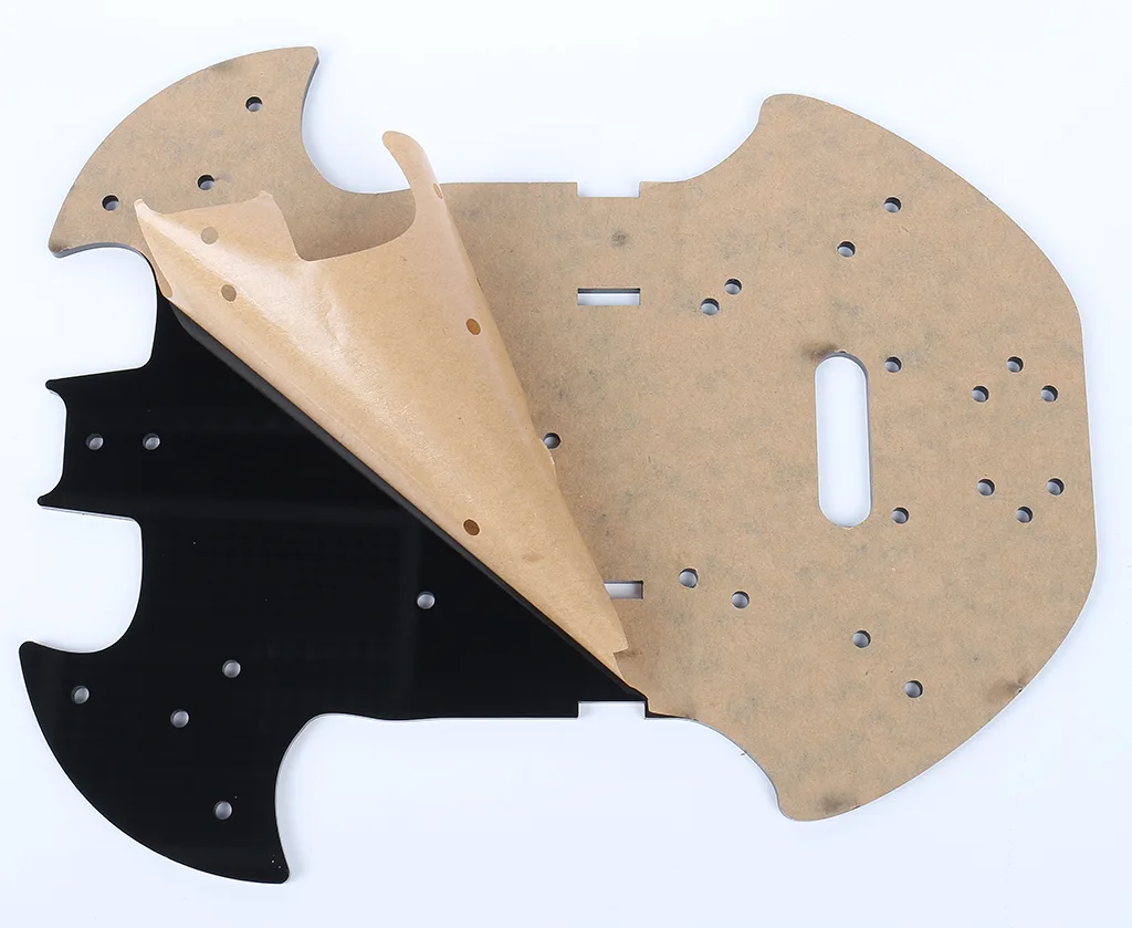
2-Place the board on the table as shown in the picture, the side with the same hole as the R3 board, we call A; the back is B. This will help you avoid mistakes during assembly.
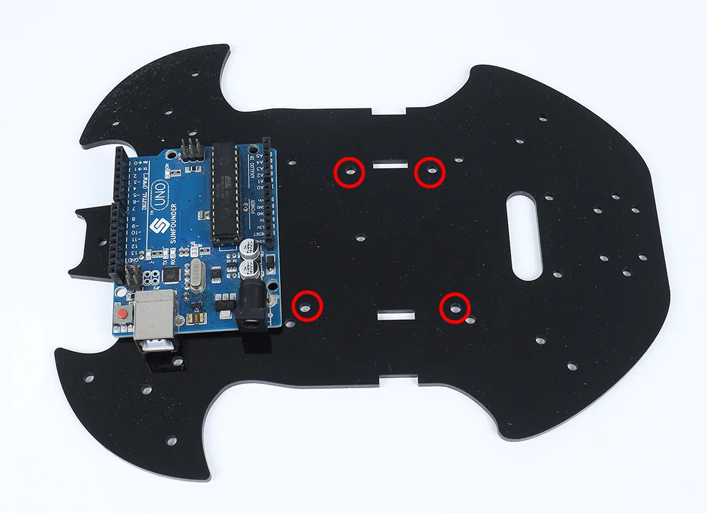
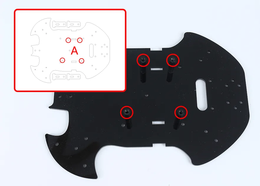
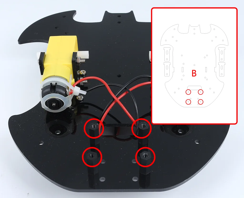
3-Mount the M3x24mm standoff with M3x6mm screws in the position as shown below.
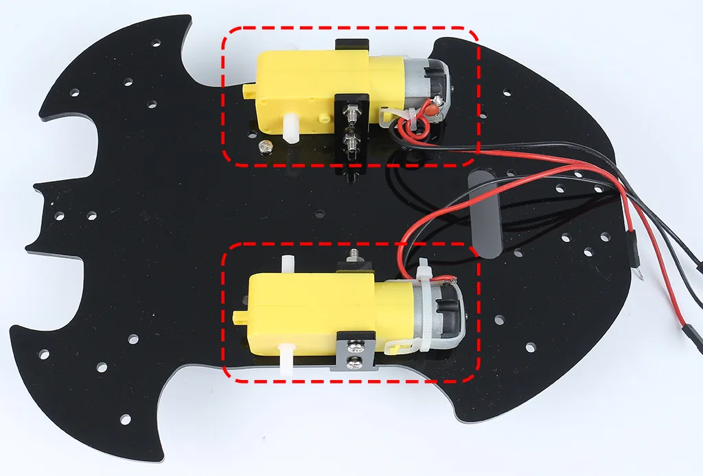
4-Turn to the B side, use M3x30mm screws and M3 nuts to attach the TT Motor. 2 details here: 1 - the output shaft is facing the bat-shaped side; 2 - the motor cable is facing the inside.
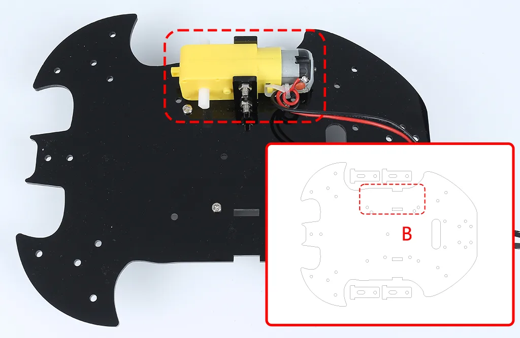
5-Mount another TT Motor, the same attention needs to be paid to the direction of the output shaft and the direction of the cable.
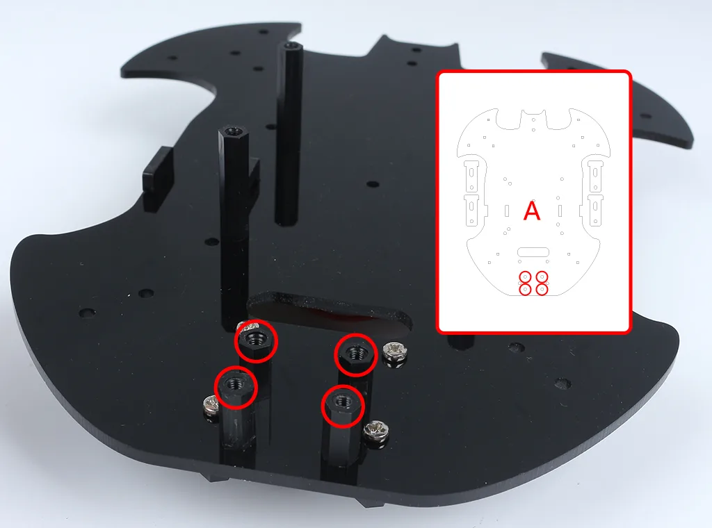
6-Use M3x6mm screws to mount the M3x12mm standoff in the position as shown below.
7-Attach the M2.5x11mm standoff to the rear of the car with M2.5x6mm screws.
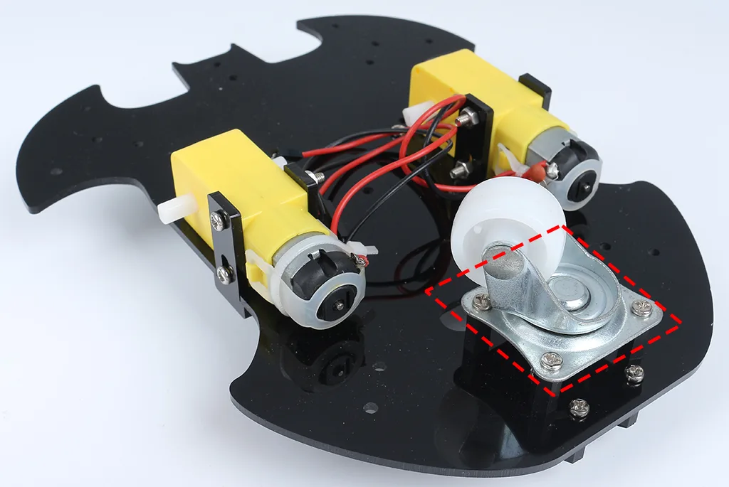
8-Use M3x6mm screws to mount the universal wheel.
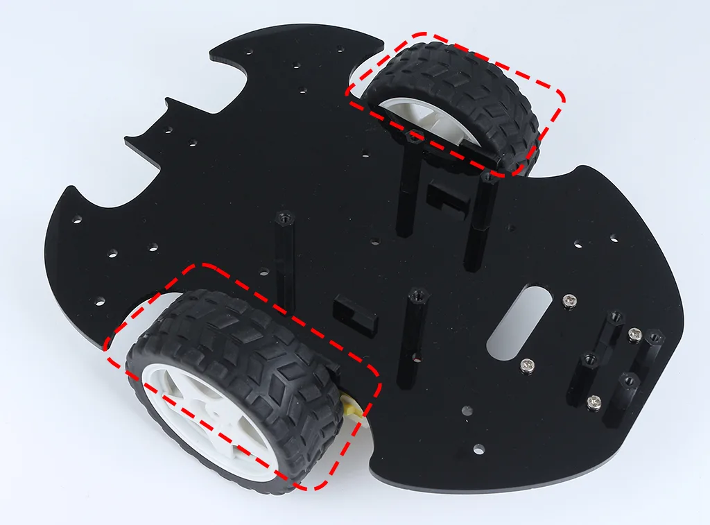
9-Putting on the 2 wheels and the car’s basic structure has been completed.
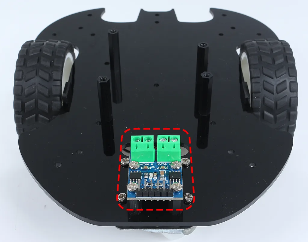
10-Attach the L9110 module with M2.5x6mm screws.
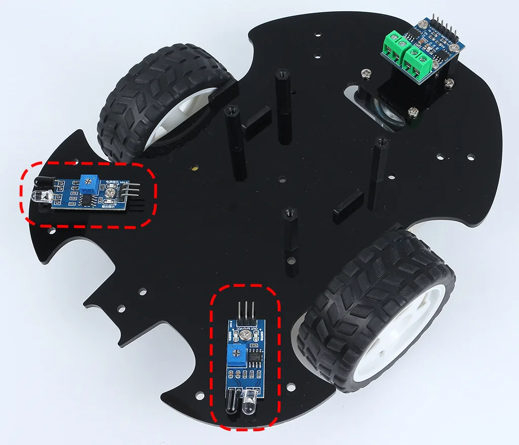
11-Assemble the two IR Obstacle Modules with M3x12mm screws and M3 nuts.
Turn to side B
Note
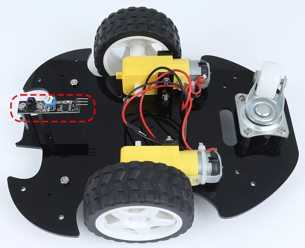
It’s advisable to first secure the M3x24mm standoffs onto the Line Track module.
One important note to keep in mind: the pins of the line sensor are slightly soft and protrude a bit towards the holes. When screwing in the M3x24mm standoffs, apply gentle pressure to push aside the sensor pins slightly.
12-Turn to side B and attach the Line Track module with four M3x6mm screws and two M3x24mm standoffs.
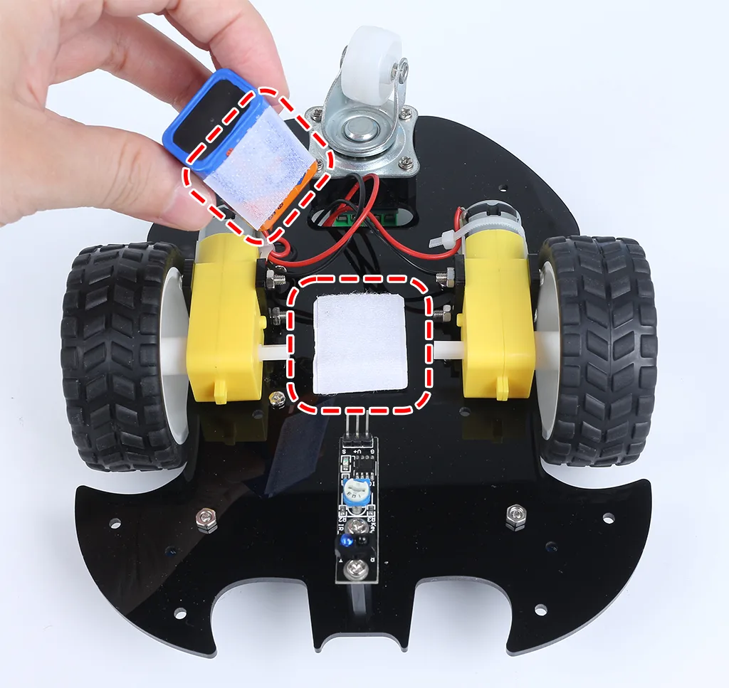
13-Stick the velcro on the 9V battery and put on the battery clip. Stick the other section of the Velcro on the car to secure the battery.
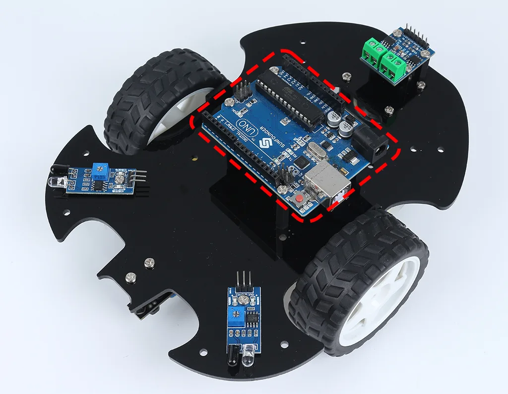
14-Turn over to side A and mount the R3 board with M3x6mm screws.
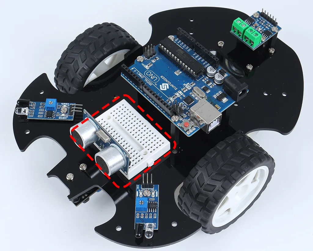
15-Attach the breadboard to the front of the car. Thereafter, you will be able to add different components (e.g. ultrasonic module) to the breadboard as required for your project.
16-Getting the car running also requires wiring it up and writing code, which will be written in subsequent sections.
Fully assembled car looks like this:
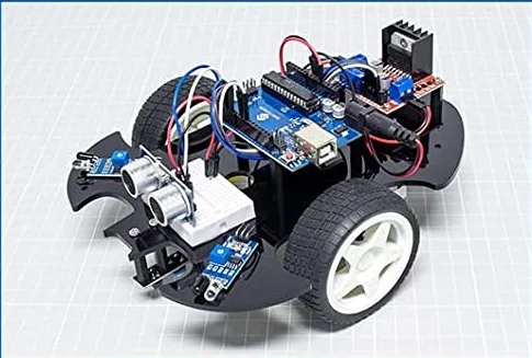
You can download the PDF manual from the files list below this article.
Images
/*
Lesson 23/31: Using Seven Segment Display
Get this code and watch video Download and resource page https://robojax.com/RJT605
YouTube video https://www.youtube.com/watch?v=3qoGAYh0lbc

*/
const int STcp = 12;//Pin connected to ST_CP of 74HC595
const int SHcp = 8;//Pin connected to SH_CP of 74HC595
const int DS = 11; //Pin connected to DS of 74HC595

int datArray[] = {0x3f,0x06,0x5b,0x4f,0x66,0x6d,0x7d,0x07,0x7f,0x6f};

void setup ()
{
  //set pins to output
  pinMode(STcp,OUTPUT);
  pinMode(SHcp,OUTPUT);
  pinMode(DS,OUTPUT);
}
void loop()
{
  for(int num = 0; num <10; num++)
  {
    digitalWrite(STcp,LOW); //ground ST_CP and hold low for as long as you are transmitting
    shiftOut(DS,SHcp,MSBFIRST,datArray[num]);
    digitalWrite(STcp,HIGH); //pull the ST_CPST_CP to save the data
    delay(1000);
  }
}
Common Course Links
Common Course Files
Things you might need
-
AmazonSunFounder Arduino Learning Kit on AliExpresss.click.aliexpress.com
-
Amazon
-
Amazon
-
Amazon
-
Amazon
Resources & references
-
DocumentationDocumentation for SunFounder 3 in 1 IoT/Smart Car/Learning Kitdocs.sunfounder.com
-
ExternalPurchase SunFounder's 3-in-1 Smart car learning kitsunfounder.com
Files📁
Arduino Libraries (zip)
-
SunFounder's 3-in-1 Smart Car learning kit source code
3in1-kit-main-v2.zip12.80 MB
User’s Manual
-
SunFounder 3-in-1 Arduino Smart Car assembly manualThis document shows step by step assembly of SunFounder 3-in-1 Arduino Smart Car
SunFounder_car_assembly_manual.pdf1.20 MB