Lesson 13/31: Using XY Joystick with Arduino and turning a buzzer with joystick Motion | Robojax
In this lesson, we explore the XY joystick module and how to interface it with an Arduino to detect directional movement and button presses. This versatile input device contains two potentiometers (one for the X-axis and one for the Y-axis) and a push button, allowing you to capture a full 360-degree range of motion along with a click action. Beyond simply reading raw values, we'll demonstrate how to trigger actions—like turning on a buzzer—when the joystick is moved into a specific position. This principle forms the foundation for countless interactive projects.
This guide is perfect for building:
- A two-axis remote control for a robotic car or pan-tilt camera mount.
- A custom game controller for a PC or mobile device.
- A menu navigation system for an LCD or OLED display.
- A precise motor speed and direction controller for industrial or hobbyist applications.
- An interactive alarm system where a specific joystick position activates a siren or alert.
Hardware and Components
To follow along with this project, you will need the following components. The specific kit used in the video is the SunFounder 3-in-1 Arduino kit, but these parts are widely available individually.
- Arduino Uno (or any compatible board)
- XY Joystick Module
- Passive Buzzer
- Jumper Wires
- USB Cable for programming and power

Understanding the XY Joystick Module
The XY joystick is a self-contained input device. As explained in the video (in video at 01:20), it combines two 10k ohm potentiometers arranged perpendicularly. Moving the stick along the X-axis rotates one potentiometer, while moving it along the Y-axis rotates the other. This allows the Arduino to read an analog voltage for each axis, representing the stick's precise position. The module also includes a momentary push button that is activated when the stick is pressed straight down.
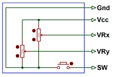
Here's a breakdown of its pins:
- GND: Connects to the ground (0V) of the Arduino.
- VCC: Connects to the 5V power supply of the Arduino.
- VRX: Analog output for the X-axis position.
- VRY: Analog output for the Y-axis position.
- SW: Digital output for the push button (active low).
The video also demonstrates that the two internal potentiometers are wired in parallel between VCC and GND, resulting in a total resistance of about 5k ohms, which is a normal reading for this module (in video at 04:30).
Wiring Guide
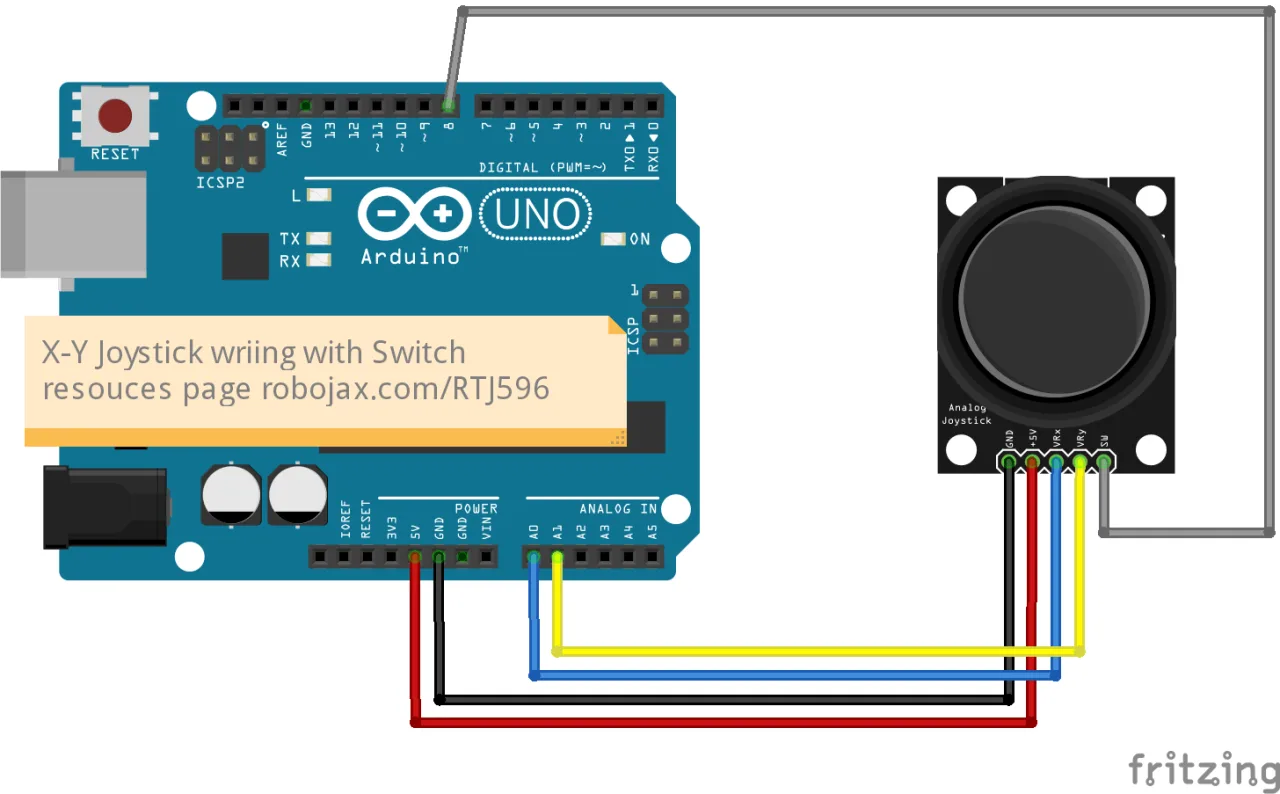
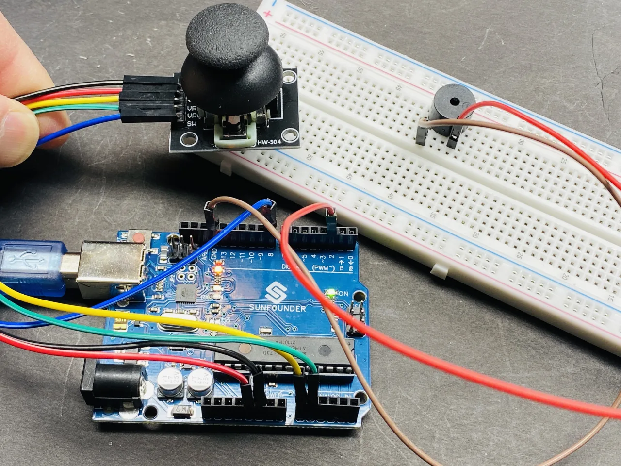
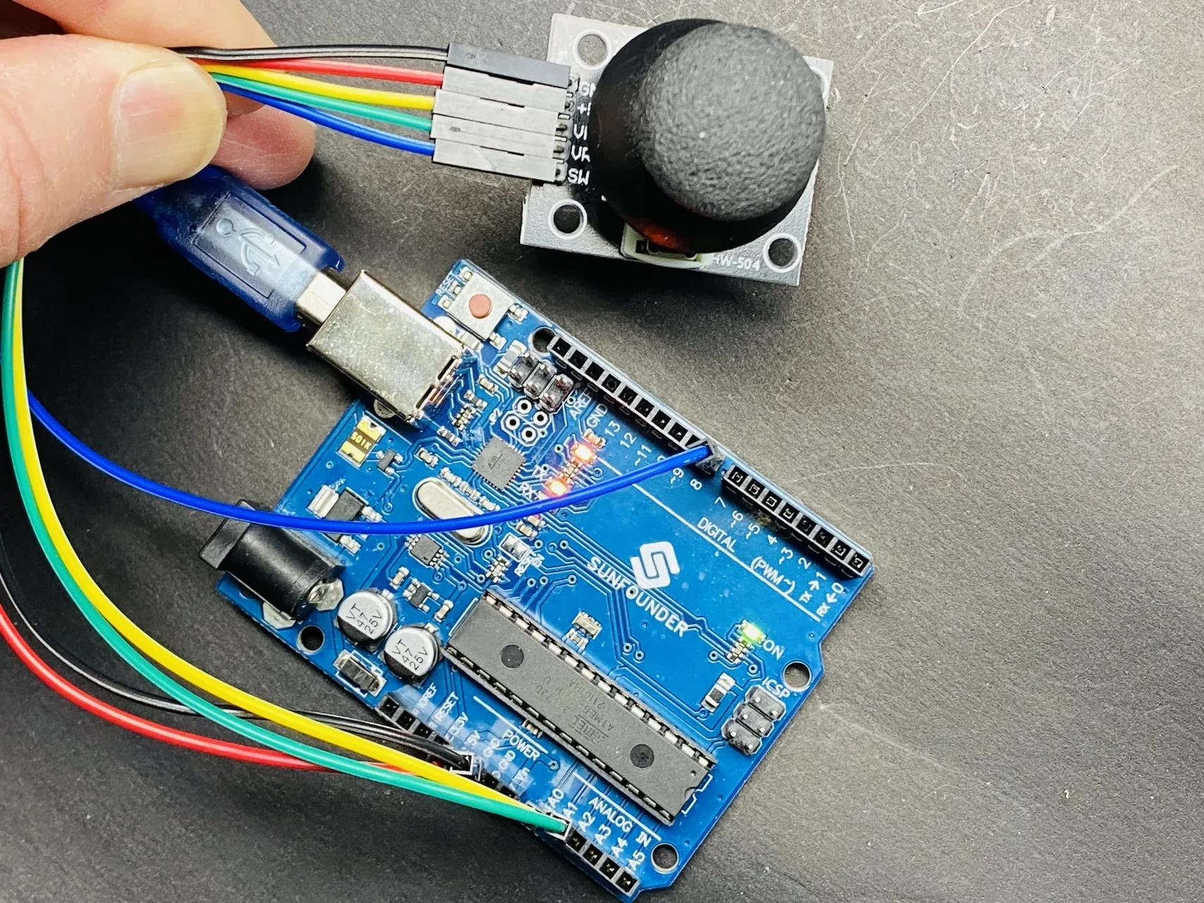
The wiring for this project is straightforward. The video shows a wiring diagram from the SunFounder documentation, but we will connect the joystick directly to the Arduino pins as described. The buzzer is added for the action part of the project.
Here are the connections as established in the video (in video at 06:24):
- Joystick GND → Arduino GND (Black wire)
- Joystick VCC → Arduino 5V (Red wire)
- Joystick VRX → Arduino A0 (Yellow wire)
- Joystick VRY → Arduino A1 (Green wire)
- Joystick SW → Arduino Pin 8 (Blue wire)
- Buzzer Positive (Long Pin) → Arduino Pin 2
- Buzzer Negative (Short Pin) → Arduino GND
Code Explanation
The provided code is designed to read the joystick's position and activate the buzzer when a specific condition is met. The key parts you can configure are at the top of the sketch.
First, the pin definitions are set. You can change these to match your specific wiring:
const int xPin = A0;  //the VRX attach to
const int yPin = A1;  //the VRY attach to
const int swPin = 8;  //the SW attach to
const int alarmPin=2;//to buzzer
Next, global variables are declared to store the joystick's state. These are updated each time the readJoystick() function is called.
int xValue;//to store xValue
int yValue;//to store yValue
int swValue;//to store value of the switch
In the setup() function, the switch pin is configured with an internal pull-up resistor. This is a crucial step because it eliminates the need for an external resistor. By setting it to INPUT_PULLUP, the pin will read HIGH by default and go LOW when the button is pressed.
pinMode(swPin, INPUT_PULLUP); //set the SW pin to INPUTThe core logic is in the loop(). It calls the custom readJoystick() function to get fresh data. Then, it checks a condition: if the X-axis value is greater than 600 and the Y-axis value is less than 300, the buzzer is turned on. You can modify these threshold values to define a different "active zone" for the joystick. The alarmPin is set HIGH to activate the buzzer and a message is printed to the Serial Monitor.
if(xValue >600 && yValue <300)
{
  digitalWrite(alarmPin, HIGH);
  Serial.print("Alarm X:");
  Serial.print(xValue);
  Serial.print(" Y:");
  Serial.println(yValue);
}else{
  digitalWrite(alarmPin, LOW);
  // ... code to print values when alarm is off
}
Finally, the custom function readJoystick() is defined. This function reads the analog values from the X and Y pins and the digital state of the switch, storing them in the global variables. This modular approach keeps the main loop clean and organized.
void readJoystick()
{
  xValue =analogRead(xPin);//read xPin value
  yValue =analogRead(yPin);//read yPin
  swValue =digitalRead(swPin);//read switch
}
Live Project and Demonstration
Once the code is uploaded, the Serial Monitor can be opened to observe the raw values. Initially, with the joystick centered, the X and Y values will be around 512, which is the midpoint of the 0-1023 range. Pressing the joystick down will change the switch value from 1 to 0 (in video at 10:15).
Moving the joystick to the extremes will show the full range: moving it fully to the right will show an X value of 1023, and fully to the left will show 0. Similarly, moving it up and down will change the Y value between 0 and 1023 (in video at 10:37).
The demonstration then shows the action part of the project. When the joystick is moved to the top-right corner (where X > 600 and Y < 300), the buzzer will sound, and the Serial Monitor will print an "Alarm" message. Moving it away from that zone will turn the buzzer off. This proves that you can use the joystick's position to control an output device, which can be extended to control relays, LEDs, or motors for various applications.
Chapters
- [00:00] Introduction to the XY Joystick Project
- [01:20] Understanding the Hardware and Internal Components
- [03:33] Module Schematic and Resistance Measurement
- [05:51] Wiring the Joystick to the Arduino
- [07:00] Setting Up the Code and Enabling Pull-up Resistor
- [09:23] Uploading Code and Testing Raw Values
- [12:21] Taking Action: Controlling a Buzzer with Joystick Position
- [16:02] Live Demonstration of the Alarm System
Images
This code has not been parsed yet. Please return to the admin panel to parse it.Common Course Links
Common Course Files
Things you might need
-
AmazonSunFounder Arduino Learning Kit on AliExpresss.click.aliexpress.com
-
Amazon
-
Amazon
-
Amazon
-
Amazon
Resources & references
-
DocumentationDocumentation for SunFounder 3 in 1 IoT/Smart Car/Learning Kitdocs.sunfounder.com
-
ExternalPurchase SunFounder's 3-in-1 Smart car learning kitsunfounder.com
Files📁
Arduino Libraries (zip)
-
SunFounder's 3-in-1 Smart Car learning kit source code
3in1-kit-main-v2.zip12.80 MB
User’s Manual
-
SunFounder 3-in-1 Arduino Smart Car assembly manualThis document shows step by step assembly of SunFounder 3-in-1 Arduino Smart Car
SunFounder_car_assembly_manual.pdf1.20 MB