In this tutorial, we will learn how to use the ESP32 module along with the line tracking module to detect black lines on a white surface. This capability is essential for applications such as robotic cars that need to follow a designated path. Additionally, we will integrate a buzzer that activates when the line tracking module detects the black line, enhancing the feedback mechanism of our project. For further clarification, please refer to the video (in video at 0:00).
line_track
Hardware Explained
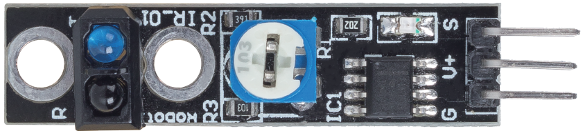
The primary components of this project include the ESP32 module, a line tracking module, and a buzzer. The ESP32 module is a powerful microcontroller featuring built-in Wi-Fi and Bluetooth capabilities, allowing for a wide range of IoT applications. The line tracking module utilizes an infrared emitter and photoresistor to detect differences in surface color based on the intensity of the reflected infrared light.
The line tracking module operates by emitting infrared light that reflects off the surface beneath it. A darker surface, like black, absorbs more light, resulting in a lower reflected intensity, while a lighter surface, like white, reflects more light, producing a higher intensity. This difference is processed by an operational amplifier to determine the state of the surface (black or white) and output a corresponding signal.
Datasheet Details
Manufacturer
SunFounder
Part number
TCRT5000
Logic/IO voltage
3.3 V to 5 V
Output current (per channel)
20 mA
Peak current (per channel)
50 mA
Response time
< 10 ms
Detection range
1 cm to 5 cm
Package
Module with header pins
Notes / variants
Commonly used in line following robots
Ensure proper power supply (3.3 V or 5 V).
Keep the sensor clean for accurate readings.
Adjust sensitivity using the onboard potentiometer.
Check connections to avoid floating inputs.
Use pull-up resistors if necessary for stable readings.
Minimize interference from ambient infrared sources.
Wiring Instructions
ESP32-20_line-tracking-wiring
To wire the line tracking module to the ESP32, start by connecting the ground pin of the module to a ground pin on the ESP32. Then, connect the V+ pin of the line tracking module to a suitable power source, either 3.3 V or 5 V on the ESP32. The signal pin (labeled as S) should be connected to GPIO 14 on the ESP32. Ensure that these connections are secure before proceeding.
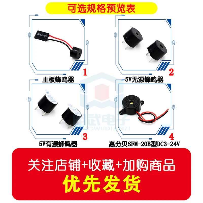
If you are using a buzzer, connect its negative terminal to the ground and the positive terminal to GPIO 27 on the ESP32. This setup allows the buzzer to activate when the line tracking module detects a black line. Make sure to double-check all connections to ensure they match the specified pins in the code.
ESP32-20_line-tracking-schemtaic
Code Examples & Walkthrough
Below is a key excerpt from the code that sets up the line tracking module. The variable linePin is defined to represent the pin connected to the line tracking module.
const int linePin = 14; // The number of the line track module pin
This line initializes linePin as pin 14, which will be used to read the line status. The lineState variable will hold the result from the sensor.
In the setup() function, we configure the pin mode for linePin as an input.
This ensures that the ESP32 can read the state of the line tracking module. The serial communication is initiated at a baud rate of 115200 for monitoring output.
Finally, in the loop() function, we continuously read the state of the line tracking module and print the detected color.
This loop checks if the lineState is HIGH (indicating black) or LOW (indicating white) and prints the result to the serial monitor. The full code loads below the article for your reference.
Demonstration / What to Expect
Once the wiring is complete and the code is uploaded, you should observe the ESP32 printing "Black" when the line tracking module is over a black surface, and "White" when it is over a white surface. Additionally, the buzzer will sound when the module detects the black line, providing an audible alert. Be cautious of the potentiometer settings, as overly sensitive settings can lead to erratic behavior (in video at 10:00).
Video Timestamps
00:00 Start
2:22 Introduction to Line tracking module
5:10 Documentation page
9:20 Wiring explained
10:49 Arduino code explained
13:36 Selecting ESP32 board and COM port in Arduino IDE