ESP32 Tutorial 52/55 - WS2812 CheerLights MQTT Global Sync with LCD | SunFounder ESP32 IoT kit
In this tutorial, we will create a CheerLights project using the ESP32, which will synchronize colors globally through MQTT. This project will not only change colors based on inputs from other users but also display the current color and how many times it has been updated on an LCD screen. The outcome is a fun demonstration of IoT capabilities, showcasing how devices can interact and keep users connected across distances. For additional clarification, watch the video at (in video at 00:00).
Hardware Explained
To build this project, you'll need an ESP32 microcontroller, a WS2812 LED strip, and an LCD display. The ESP32 serves as the brain of the operation, utilizing its built-in Wi-Fi capabilities to connect to the internet and receive MQTT messages. This allows real-time updates to the LED colors based on a global input from other users.
The WS2812 LED strip is a popular choice for projects requiring addressable RGB LEDs. Each LED can be controlled independently, allowing for rich color displays. The LCD will provide a visual confirmation of the current color and the number of times it has been changed, enhancing user interaction.

Datasheet Details
| Manufacturer | SunFounder |
|---|---|
| Part number | ESP32 |
| Logic/IO voltage | 3.3 V |
| Supply voltage | 5 V |
| Output current (per channel) | 20 mA |
| Peak current (per channel) | 60 mA |
| PWM frequency guidance | 400 Hz |
| Input logic thresholds | 0.15 V (low), 0.8 V (high) |
| Voltage drop / RDS(on) / saturation | 0.2 V |
| Thermal limits | 85 °C |
| Package | ESP32 module |
| Notes / variants | Includes built-in Wi-Fi and Bluetooth |
- Ensure proper power supply to the ESP32 (5 V) and WS2812 strip (5 V).
- Use a common ground between the ESP32 and the LED strip.
- Implement a proper MQTT broker for color synchronization.
- Pay attention to the data pin connection for the WS2812 (pin 14 as per the code).
- Be cautious with the number of LEDs; exceeding the power limits requires additional power sources.
Wiring Instructions


To wire the components, start by connecting the WS2812 LED strip. Connect the ground pin (usually black) of the LED strip to the ground pin on the ESP32. Next, connect the VCC pin (usually red) of the LED strip to the 5V output on the ESP32. Finally, connect the data pin (often yellow) to GPIO pin 14 on the ESP32.
For the LCD, connect the ground pin (often black) to the ground on the ESP32. The VCC pin (usually red) should be connected to the 5V output. The SDA pin (typically gray) connects to GPIO pin 21, while the SCL pin (usually white) connects to GPIO pin 22. This setup allows the ESP32 to communicate with the LCD and display information as needed.
Code Examples & Walkthrough
In the setup function, we initialize the LCD and connect to Wi-Fi. The code below demonstrates how to define the necessary libraries and set up the LCD:
#include
#include
LiquidCrystal_I2C lcd(0x27, 16,2);  // set the LCD address
void setup() {
  Serial.begin(115200);
  lcd.init(); // initialize the lcd
  lcd.backlight(); // Turns on the LCD backlight.
}
This initializes the LCD for use, allowing it to display messages. The next excerpt shows how the Wi-Fi connection is established:
void setup_wifi() {
  WiFi.begin(ssid, password);
  while (WiFi.status() != WL_CONNECTED) {
    lcdConnect(); //for LCD
    delay(500);
  }
  Serial.println("WiFi connected");
}
This function establishes a connection to the specified Wi-Fi network, displaying a message on the LCD while connecting. Lastly, the color change logic is handled in the callback function:
void callback(char* topic, byte* message, unsigned int length) {
  String messageTemp;
  for (int i = 0; i < length; i++) {
    messageTemp += (char)message[i];
  }
  if (String(topic) == "cheerlights") {
    setColor(messageTemp);
  }
}
This function listens for incoming messages on the "cheerlights" topic and updates the color accordingly. The full code loads below the article, so make sure to review it for the complete implementation.
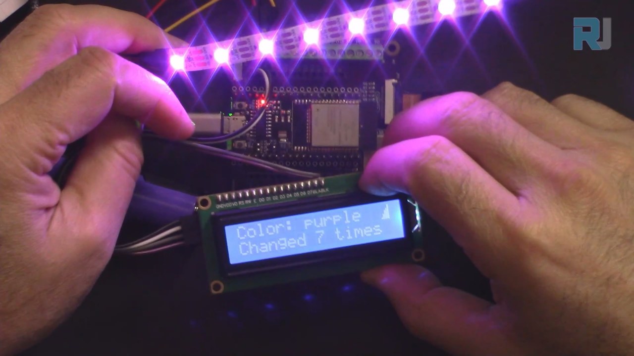
Demonstration / What to Expect
Upon completion of the project, you can expect the LED strip to change colors based on inputs from a global MQTT feed. The LCD will display the current color name and how many times it has been changed. If you disconnect the internet, the LCD will indicate "Connecting..." until a connection is re-established (in video at 12:30).
Common pitfalls include ensuring that the correct pins are used for data connections and verifying that the Wi-Fi credentials are accurate. If there are any discrepancies in the SSID or password, the ESP32 will fail to connect, and the LCD will continue to display the connecting message.
Video Timestamps
- 00:00 Start
- 1:59 Introduction to the project
- 6:16 Wiring explained
- 8:13 Arduino Code explained
- 14:26 Selecting ESP32 board and COM port on Arduino IDE
- 16:07 CheerLight Demonstration with LCD
图像
/*
 * 这是来自SunFounder的Examples->iot_5_cheerlight的原始代码
 * 完整的视频说明 https://youtu.be/xEqmxMiF-E8
 * 📚⬇️ 下载和资源页面 https://robojax.com/RJT685
 *
 * 我添加了LCD来显示:
 * 1-颜色名称
 * 2-更新颜色的次数
 * 3-如果连接到wifi则在LCD上显示
 * 4-如果未连接或断开连接则显示连接中
 *
 * 作者:Ahmad Shamshiri
 * www.Robojax.com
 * 2023年12月29日
 *
 * :ref: https://randomnerdtutorials.com/esp32-mqtt-publish-subscribe-arduino-ide/
 * https://docs.sunfounder.com/projects/kepler-kit/en/latest/iotproject/5.mqtt_pub.html
 */
#include <Wire.h>
#include <LiquidCrystal_I2C.h>

 // SDA->21,SCL->22
LiquidCrystal_I2C lcd(0x27, 16,2); // 将LCD地址设置为0x27,用于16字符和2行显示。

int colorCount = 0;
int lastColor=0;

byte connected[] = {
          B00001,
          B00001,
          B00011,
          B00111,
          B00111,
          B01111,
          B01111,
          B11111
};


#include <WiFi.h>
#include <PubSubClient.h>
 // #include <Wire.h>
#include <Adafruit_NeoPixel.h>


 // 用您的SSID/密码组合替换下列变量
const char* ssid = "dars";
const char* password = "5152535455";

 // 添加您的 MQTT 代理地址:
const char* mqtt_server = "mqtt.cheerlights.com";
const char* unique_identifier = "sunfounder-client-sdgvsasdda";

WiFiClient espClient;
PubSubClient client(espClient);
long lastMsg = 0;
int value = 0;


 // 定义支持的CheerLights颜色及其RGB值。
String colorName[] = {"red", "pink", "green", "blue", "cyan", "white", "warmwhite", "oldlace", "purple", "magenta", "yellow", "orange"};

int colorRGB[][3] = { 255,   0,   0, // 红色
                      255, 192, 203, // 粉色
                        0, 255,   0, // 绿色
                        0,   0, 255, // 蓝色
                        0, 255, 255, // 青色
                      255, 255, 255, // 白色
                      255, 223, 223, // 暖白色
                      255, 223, 223, // 老花色
                      128,   0, 128, // 紫色
                      255,   0, 255, // 品红色
                      255, 255,   0, // 黄色
                      255, 165,   0}; // 橙子

 // 初始化rgb灯带
#define LED_PIN 13
#define NUM_LEDS 8

Adafruit_NeoPixel pixels = Adafruit_NeoPixel(NUM_LEDS, LED_PIN, NEO_GRB + NEO_KHZ800);

void setup() {
  Serial.begin(115200);

  lcd.init(); // 初始化 LCD
  lcd.backlight(); // 打开LCD背光。

 // wifi 默认设置
  setup_wifi();
  client.setServer(mqtt_server, 1883);
  client.setCallback(callback);

 // rgb灯带开始
  pixels.begin();
  pixels.show();

}

void setup_wifi() {
  delay(10);
 // 我们首先连接到一个WiFi网络。
  Serial.println();
  Serial.print("Connecting to ");
  Serial.println(ssid);

  WiFi.begin(ssid, password);

  while (WiFi.status() != WL_CONNECTED) {
    lcdConnect(); // 用于LCD
    delay(500);
    Serial.print(".");
  }

  Serial.println("");
  Serial.println("WiFi connected");
  Serial.println("IP address: ");
  Serial.println(WiFi.localIP());
}

void callback(char* topic, byte* message, unsigned int length) {
  Serial.print("Message arrived on topic: ");
  Serial.print(topic);
  Serial.print(". Message: ");
  String messageTemp;

  for (int i = 0; i < length; i++) {
    Serial.print((char)message[i]);
    messageTemp += (char)message[i];
  }
  Serial.println();

 // 如果在该主题上收到消息,您将检查这条消息。
 // 根据消息改变输出状态。
  if (String(topic) == "cheerlights") {
    Serial.print("Changing color to ");
    Serial.println(messageTemp);
    setColor(messageTemp);
  }
}

void reconnect() {
 // 循环直到我们重新连接。
  while (!client.connected()) {
  lcdConnect();
    Serial.print("Attempting MQTT connection...");
 // 尝试连接
    if (client.connect(unique_identifier)) {
      Serial.println("connected");
 // 订阅
      client.subscribe("cheerlights");
    } else {
      Serial.print("failed, rc=");
      Serial.print(client.state());
      Serial.println(" try again in 5 seconds");
 // 请等5秒再重试。
      delay(5000);
    }
  }
}

void setColor(String color) {
 // 循环遍历颜色列表以查找匹配的颜色
  for (int colorIndex = 0; colorIndex < 12; colorIndex++) {
    if (color == colorName[colorIndex]) {
        lastColor = colorIndex; // 记住最后的颜色
        colorCount++; // 增加计数
 // 设置条形灯带上每个NeoPixel的颜色
      for (int pixel = 0; pixel < NUM_LEDS; pixel++) {
        pixels.setPixelColor(pixel, pixels.Color (colorRGB [colorIndex][0], colorRGB [colorIndex][1], colorRGB [colorIndex][2]));
        delay(100);
      }
      pixels.show();
    }
  }
}

void lcdConnect()
{
    lcd.clear();
    lcd.setCursor(0, 0); // 线 0
    lcd.print("Connecting...");
    lcd.setCursor(0, 1);
    lcd.print("SSID:"); // 第一行
    lcd.print(ssid);
}

void loop() {
  lcd.clear();

  if (!client.connected()) {
    reconnect();
  }else{
    lcd.createChar(0, connected);
    lcd.setCursor(15, 0);
    lcd.write(byte(0));
  }
  client.loop();


 // 第一行
  lcd.setCursor(0, 0);
  lcd.print("Color: ");
  lcd.print(colorName[lastColor]);

 // 第二排
  lcd.setCursor(0, 1);
  lcd.print("Changed ");
  lcd.print(colorCount);
  lcd.print(" times");

  delay(1000); // 我们必须有延迟才能读懂显示屏。


}
Common Course Links
Common Course Files
资源与参考
-
文档ESP32 教程 52/55 - SunFounder CheerLight 文档页面docs.sunfounder.com
文件📁
没有可用的文件。