ESP32 Tutorial 50/55 - Control RGB LED from anywhere in the world | SunFounder's ESP32 kit
In this tutorial, we will learn how to control the color of an RGB LED using the ESP32 microcontroller over Wi-Fi, utilizing the MQTT protocol and Adafruit IO service. This setup allows you to change the color of the RGB LED from anywhere in the world, providing a practical application of IoT technology. We will also explore how to use sliders and a color picker to select the desired color.

The ESP32 is a powerful microcontroller that has built-in Wi-Fi and Bluetooth capabilities, making it ideal for IoT projects. In this build, we will connect an RGB LED to the ESP32 and control its color through an MQTT broker provided by Adafruit. The tutorial will guide you through the hardware setup, wiring instructions, and the code necessary to make everything work seamlessly (in video at 00:00).
Hardware Explained
For this project, the primary components we will use are the ESP32 microcontroller and the RGB LED. The ESP32 is capable of connecting to Wi-Fi networks, allowing it to communicate with the Adafruit IO service. The RGB LED contains three individual LEDs (red, green, and blue) that can be mixed to create a wide range of colors.
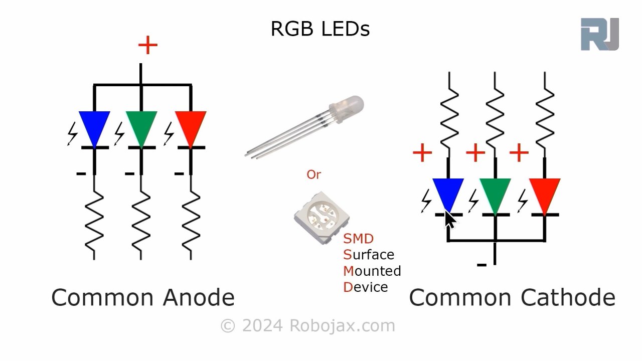
The RGB LED operates on a common anode or common cathode principle, which means that the anode (positive) or cathode (negative) of the individual LEDs must be connected properly for them to work. Each color can be controlled using Pulse Width Modulation (PWM), which adjusts the brightness of each LED by varying the duty cycle.

Datasheet Details
| Manufacturer | SunFounder |
|---|---|
| Part number | RGB LED |
| Forward voltage (VF) | 2.0–3.4 V |
| Forward current (IF) | 20 mA |
| Peak wavelength (nm) | Red: 620, Green: 525, Blue: 465 |
| Package | Standard 4-pin |
| Notes / variants | Common anode or common cathode options available |
- Use 220 ohm resistors for each LED color to limit current.
- Ensure correct wiring for common anode or cathode configuration.
- Check the ESP32's power supply to avoid brownouts.
- Keep the PWM frequency within the limits for smooth color transitions.
- Ensure Wi-Fi credentials are correct to connect to the Adafruit IO service.
Wiring Instructions
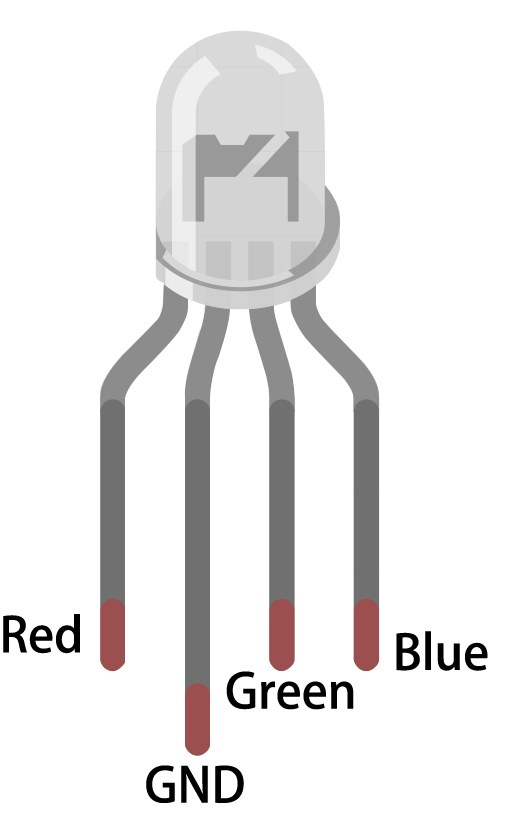
To wire the RGB LED to the ESP32, start by identifying the pins on the RGB LED. The longest pin is the common pin. For a common anode configuration, connect this pin to the positive voltage supply (3.3V). The other three pins correspond to the red, green, and blue LEDs. Connect the red pin to GPIO 27, the green pin to GPIO 26, and the blue pin to GPIO 25. Each of these connections should be made through a 220 ohm resistor to limit the current flowing through the LEDs.
Next, connect the ground (GND) of the ESP32 to the ground line of your circuit. Ensure that the wiring is secure to prevent any intermittent connections. If using a common cathode RGB LED, connect the common pin to ground instead and connect the individual color pins to the positive supply through the resistors. Double-check all connections before powering the circuit.
Code Examples & Walkthrough
In the Arduino code, we start by defining the pins for the red, green, and blue LEDs using the identifiers redPin, greenPin, and bluePin. Additionally, we define the PWM channels for each color using redChannel, greenChannel, and blueChannel. The PWM frequency is set to 5000 Hz with an 8-bit resolution.
const int redPin = 27;
const int greenPin = 26;
const int bluePin = 25;

const int redChannel = 0;
const int greenChannel = 1;
const int blueChannel = 2;
In the setup() function, we initialize the PWM channels and attach the corresponding pins. We also connect to the Wi-Fi network using the defined credentials and set up the MQTT client for communication with Adafruit IO.
void setup() {
  ledcSetup(redChannel, freq, resolution);
  ledcAttachPin(redPin, redChannel);
  // Connect to WiFi
  WiFi.begin(WLAN_SSID, WLAN_PASS);
}
The main loop checks the MQTT connection and processes incoming messages. It also prints the current RGB values to the serial monitor. The color of the LED is updated based on the values received through MQTT subscriptions.
void loop() {
  MQTT_connect();
  mqtt.processPackets(500);
  setColor();
}
For more details on the full code, please refer to the complete code loaded below the article.
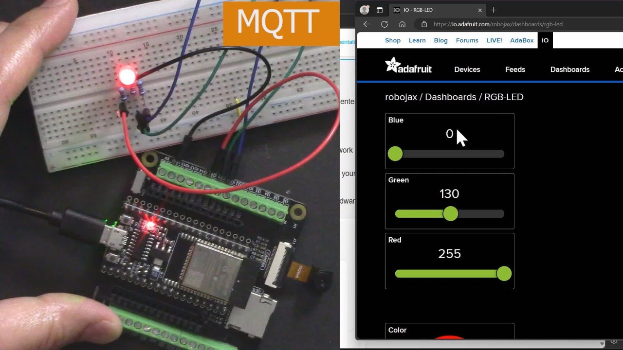
Demonstration / What to Expect
Once everything is set up and the code is uploaded, you should see the RGB LED responding to color changes made through the Adafruit IO dashboard. As you adjust the sliders for red, green, and blue, the LED should change its color accordingly. If you experience any issues, ensure that the Wi-Fi connection is stable and that the MQTT topic names match those defined in the code (in video at 17:30).
Common pitfalls include incorrect wiring, mismatched topic names, and forgetting to set the correct Wi-Fi credentials. If the LED does not light up, double-check the resistor connections and ensure that the ESP32 is powered correctly.
Video Timestamps
- 00:00 Start
- 2:23 Introduction to the project
- 4:43 What is MQTT
- 7:55 Adafruit IO setup
- 14:09 Wiring explained
- 16:07 Code explained
- 27:03 Selecting ESP32 board and COM port on Arduino IDE
- 29:12 Project demonstration
- 31:25 What is RGB LED?
- 35:26 RGB Color
图像
This code has not been parsed yet. Please return to the admin panel to parse it.Common Course Links
Common Course Files
资源与参考
尚无可用资源。
文件📁
没有可用的文件。