
Automation: Using 12V Relay with LED Display Delay Timer module P1 to P4
Automation: How to use 12V Relay with LED Display Delay Timer module P1 to P4
In this video you will learn how to use the 12V LED programmable Display Delay timer module can be programmed 0.1 seconds to 999 seconds (17 minutes) . This a greatautomation project.
Main Specifications
- Minimum time set: 0.1 second
- Maximum time set: 999 seconds
- Maximum time set: 17 minutes
- Power supply: 12V
- Power Consumption (max when all digits display 888 and relay ON): 300mA
- Power Consumption (min when singl digit zero is displayed): 100mA
- Dimensions: 64.2mm * 34.8mm * 18.5mm
- Trigger voltage: Source: DC4V ~ 20V (positive trigger common power button, PNP sensors, PLC signals, etc.)
- Relay load control: DC or AC 220v 5A within 30v 5A (or see rating printed on the relay)
Chapters of this video
- -Device is explained.
- -Wiring is explained at 03:20
- -P-1 (program 1 is explained at 04:48
- -P-2 (program 2 is explained at 08:22
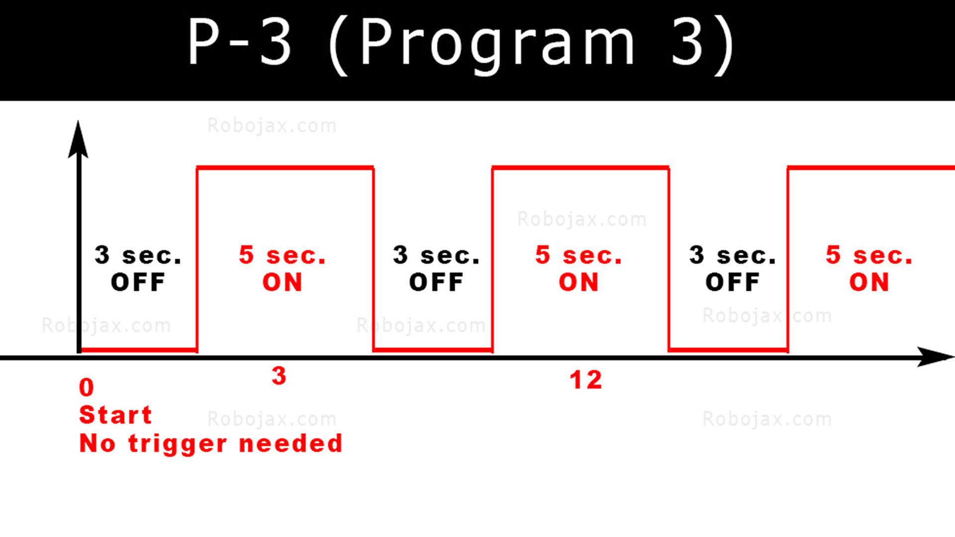
- -P-3 (program 3 is explained at 11:48
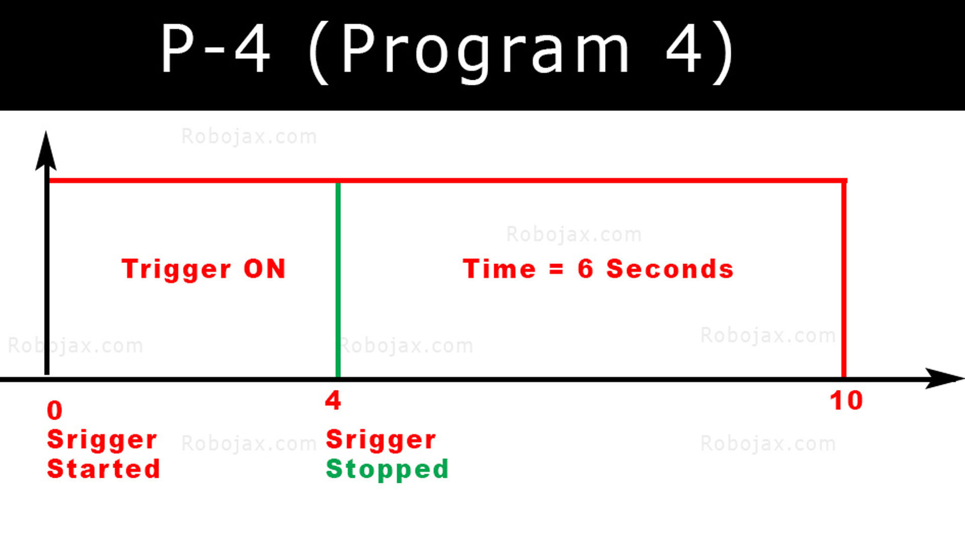
- -P-4 (program 4 is explained at 13:58
Where to buy it?
-Search eBay (no affiliation) Here-Search Amazon (no affiliation) Here
-Search AliExpress (no affiliation) Here
-Search Banggood (no affiliation) Here
Browser Screenshot Gallery
Click on the images below:
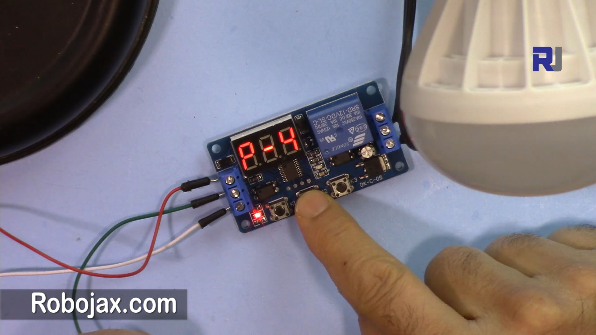
12V LED Relay Delay Timer: Main view
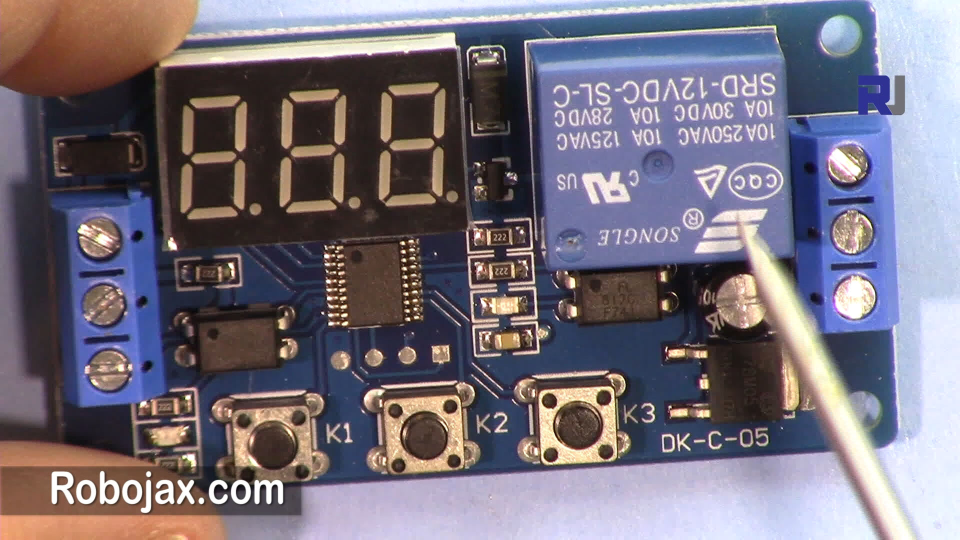
Click on image to enlarge
12V LED Relay Delay Timer: P-1 on screen
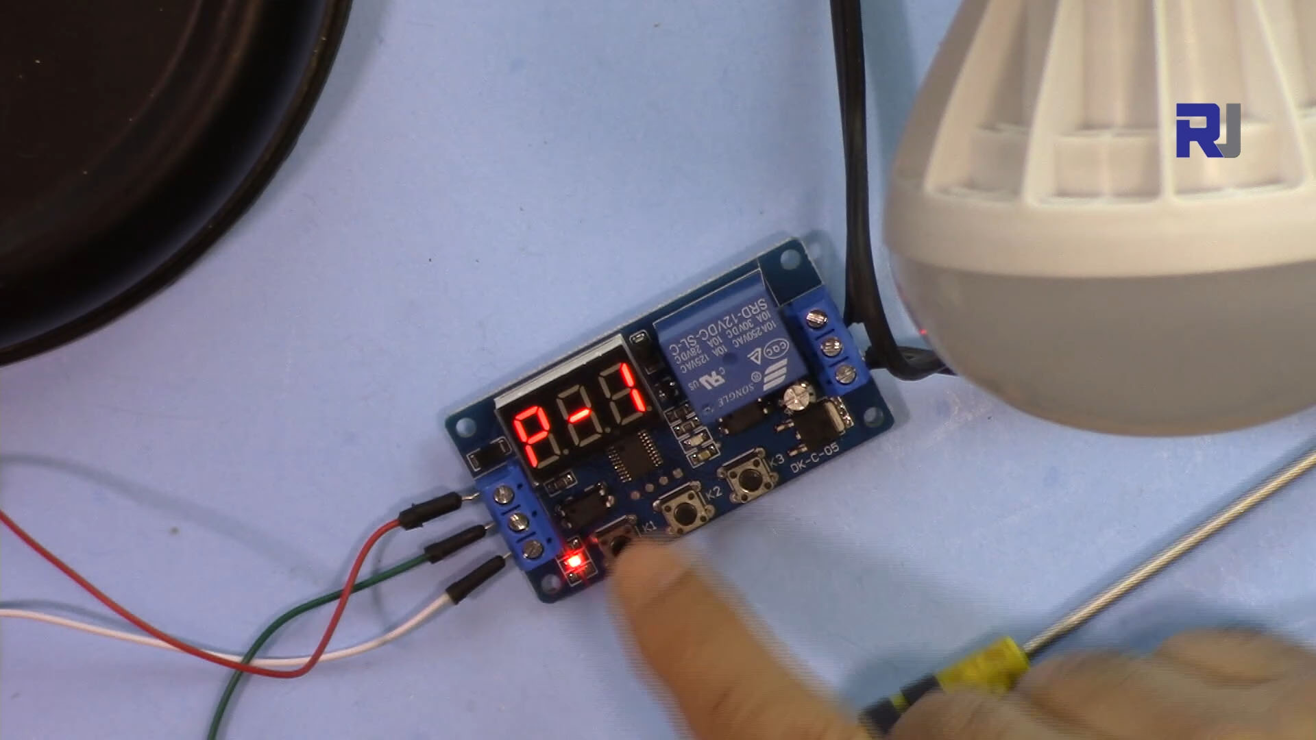
Click on image to enlarge
12V LED Relay Delay Timer: P-1 Timing
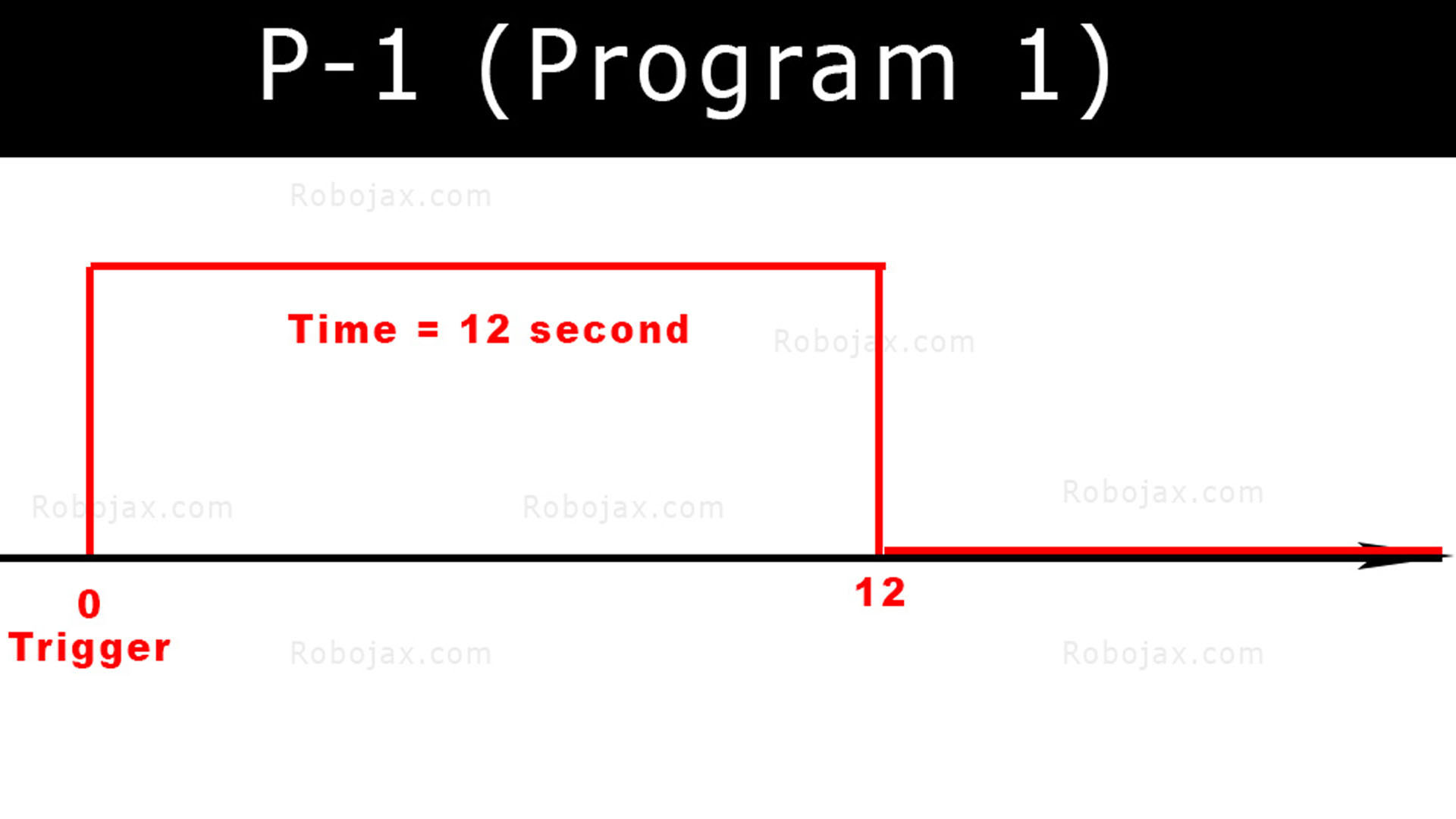
Click on image to enlarge
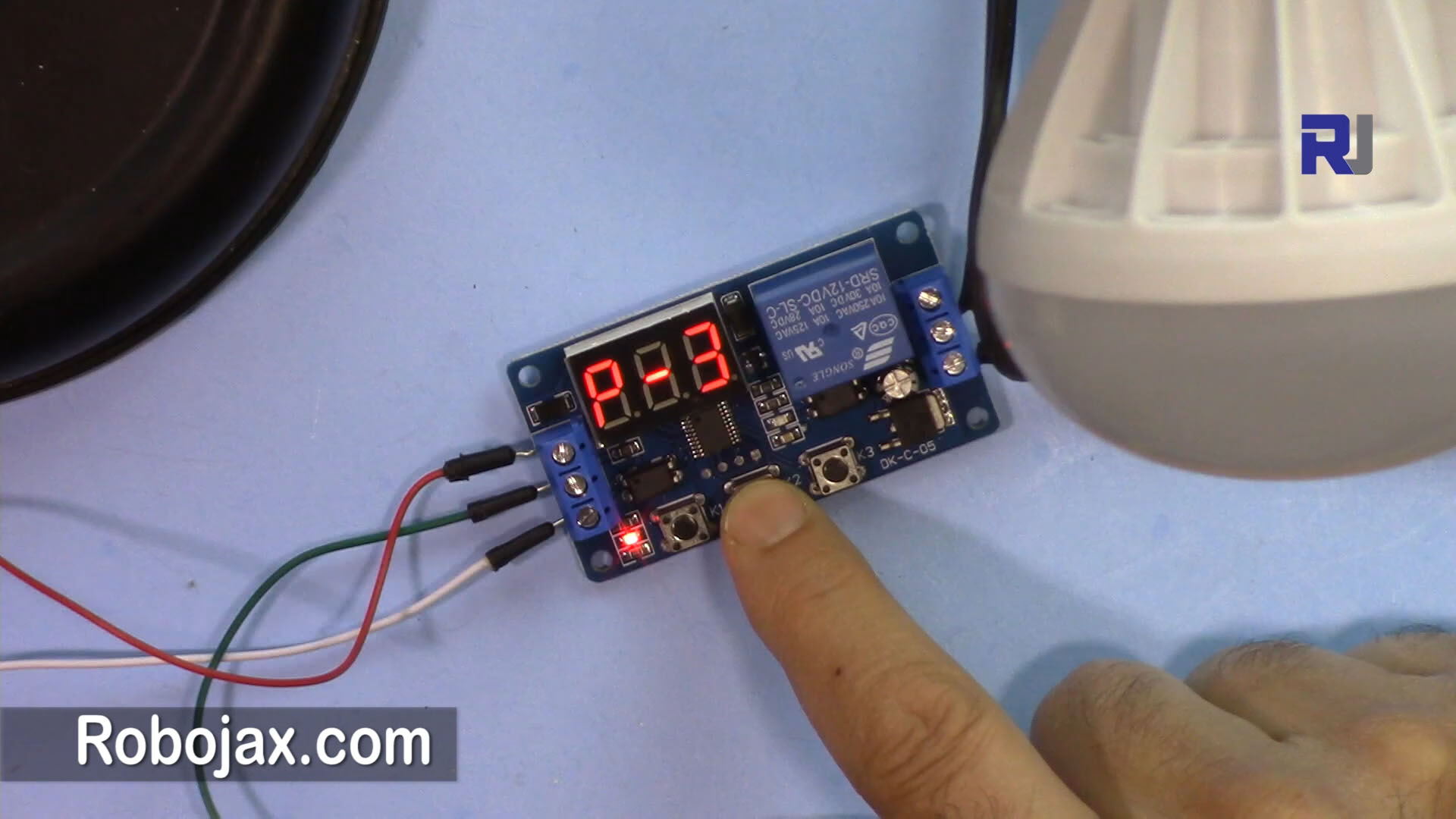
12V LED Relay Delay Timer: AC bulb turned ON

Click on image to enlarge
12V LED Relay Delay Timer: P-2 Timing

Click on image to enlarge
12V LED Relay Delay Timer: P-3 on screen
Click on image to enlarge
12V LED Relay Delay Timer: P-3 Timing
Click on image to enlarge
12V LED Relay Delay Timer: P-4 on screen
Click on image to enlarge
12V LED Relay Delay Timer: P-4 Timing
Click on image to enlarge