This tutorial is part of: Controlling 16 or 32 Servo motor with PCA9685
These collection of tutorial with video help you control 32 or more servo motors using Arduino UNO, Nano, Mini or ESP32 . All codes provided

Controlling a 32 Servo Motor Using a PCA9685 Module and Arduino V3 Sketch #1: All Servos Together
In this tutorial, we will learn how to control 32 servo motors using two PCA9685 PWM driver modules connected to an Arduino. The PCA9685 is a versatile module that allows for easy control of multiple servos via I2C communication. By the end of this project, you'll be able to move all 32 servos in unison with a simple setup.

We will also implement a push button that can turn all the servos on or off simultaneously. This feature adds an extra layer of control and makes the project more interactive. For a visual understanding of the setup and code, be sure to check out the accompanying video (in video at 00:00).
Hardware Explained
The key component in this project is the PCA9685 module, which provides 16 channels for PWM signals. This module uses I2C communication, with the SDA and SCL pins handling data transmission. Each PCA9685 can control up to 16 servos, but by cascading two modules, we can control 32 servos simultaneously.
The Arduino serves as the controller, sending commands to the PCA9685 modules. Each servo motor will be connected to one of the output pins on the PCA9685, allowing for precise control over their positions. Proper external power supply is crucial, as the servos can draw significant current.
Datasheet Details
| Manufacturer | Adafruit |
|---|---|
| Part number | PCA9685 |
| Logic/IO voltage | 3.3 V to 5.5 V |
| Supply voltage | 5 V (external for servos) |
| Output current (per channel) | ~20 mA |
| Peak current (per channel) | ~25 mA |
| PWM frequency guidance | 40 Hz to 1000 Hz |
| Input logic thresholds | 0.3 V (low), 0.7 V (high) |
| Voltage drop / RDS(on) / saturation | ~0.5 V |
| Thermal limits | Operating temperature: -40°C to +85°C |
| Package | 16-pin TSSOP |
| Notes / variants | Can chain multiple boards for expanded control |
- Ensure appropriate power supply to avoid servo stalling.
- Use external power for servos; Arduino cannot supply sufficient current.
- Connect ground of the PCA9685 to the Arduino ground.
- Keep the OE pin grounded to enable the module.
- Note the I2C address for each module; default is 0x40 for the first and 0x41 for the second.
Wiring Instructions

To wire the PCA9685 modules and servos, start by connecting the power and ground. Connect the VCC pin on the PCA9685 to the 5V pin on the Arduino, and connect the ground pin to the Arduino's GND. For the servo power, use an external power supply connected to the V+ pin on the PCA9685.
Next, connect the SDA and SCL pins of the PCA9685 modules to the Arduino's A4 and A5 pins, respectively. If you are using multiple PCA9685 modules, connect them in a daisy chain. Ensure that the OE pin is connected to ground to enable the outputs. Finally, connect each servo's signal wire to the respective PWM output pins on the PCA9685 (0-15 for the first module and 16-31 for the second module).
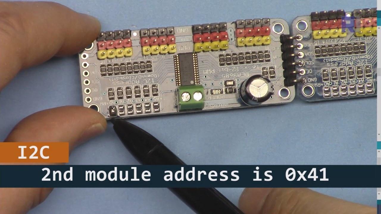
As shown int he image bove you must solder the pins shown on board 2 and must be different from the board 1. This way we wil l have different i2C address and you can control the board.
Code Examples & Walkthrough
Let's take a look at the setup portion of the code that initializes the PCA9685 modules. This is where we define the addresses for each board:
Adafruit_PWMServoDriver board1 = Adafruit_PWMServoDriver(0x40);
Adafruit_PWMServoDriver board2 = Adafruit_PWMServoDriver(0x41);
In this excerpt, we create instances of the PCA9685 driver for both boards, specifying their I2C addresses. This setup is crucial for ensuring that our Arduino can communicate with both modules.
The setup() function initializes the boards and sets the PWM frequency:
void setup() {
  Serial.begin(9600);
  board1.begin();
  board2.begin();
  board1.setPWMFreq(60);  // Analog servos run at ~60 Hz updates
  board2.setPWMFreq(60);
}
Here, we start the serial communication and set both boards to operate at a frequency of 60 Hz, which is standard for most servos. This ensures smooth operation as we control the servos.
Next, let's look at the control logic in the loop() function:
for(int angle = 0; angle < 181; angle += 10) {
  for(int i = 0; i < 16; i++) {
    board1.setPWM(i, 0, angleToPulse(angle));
    board2.setPWM(i, 0, angleToPulse(angle));
  }
}
This loop increments the angle from 0 to 180 degrees in steps of 10. For each angle, it sets the PWM signal for all servos on both boards, allowing them to move in unison from 0 to 180 degrees and back. The angleToPulse() function converts the angle to the corresponding pulse width for the servos.
Demonstration / What to Expect
Once everything is wired and the code is uploaded, you should see all 32 servos moving together, stepping through the angles smoothly. If you press the push button, it will toggle the state of all servos between on and off (in video at 00:00). Be cautious of reversed polarity and ensure that your servos are rated for the current supplied to avoid overheating.
Video Timestamps
- 00:00 Start
- 01:18 Introduction
- 04:30 Preparing to modules
- 07:56 wiring explained
- 10:25 Power requirement
- 11:33 Code Explained
- 19:54 Code 2 Explained (8 servo together on each boards)
- 20:40 Demonstration 8 servo control together
- 21:55 Demonstration All 32 Servo move together
- 22:28 Code for push button explained
- 24:43 Wiring for push button explained
- 25:12 Demonstration of using push button switch
Images


This tutorial is part of: Controlling 16 or 32 Servo motor with PCA9685
- Arduino Code and Video for PCA9685 16-Channel 12-Bit Servo Controller V1
- Control 16 Servo Motors Using a PCA9685 Module and Arduino V2 Sketch #1: One-by-One
- Controlling 16 Servo Motors Using a PCA9685 Module and Arduino V2 Sketch: Individual Servo Control
- Controlling 16 Servo Motors Using a PCA9685 Module and Arduino V2 Sketch #3: All Servos Together
- Controlling a 32 Servo Motor Using a PCA9685 Module and an ESP32 V4
- Control 32 Servos over Wi-Fi Using ESP32 and PCA9685 via Desktop or Mobile Phone V5
This code has not been parsed yet. Please return to the admin panel to parse it.This code has not been parsed yet. Please return to the admin panel to parse it.This code has not been parsed yet. Please return to the admin panel to parse it.Things you might need
-
AmazonPurchase PCA9685 from Amazonamzn.to
-
eBayPurchase PCA9685 from eBayebay.us
-
AliExpressPurchase PCA9685 from AliExpresss.click.aliexpress.com
-
BanggoodPurchase PCA9685 from Bangoodbanggood.com
Resources & references
No resources yet.
Files📁
Arduino Libraries (zip)
-
Adafruit-PWM-Servo-Driver-Library-master
Adafruit-PWM-Servo-Driver-Library-master.zip0.02 MB