
Pro Micro ATMEGA32U4 Arduino Pins and 5V, 3.3V Explained
Pro Micro ATMEGA32U4 Arduino Pins and 5V, 3.3V Explained
In this video, you will learn about Pro Micro ATMEGA32U4 Arduino board and how to connect it external power or USB. Digital and analog pins explained PWM is tested.
Pro Micro Driver. You should not need driver as Arduino IDE has all the drivers for this board. It is located inside your Arduino folder: arduino-1.x.x\drivers
Where x is your version of Arduino IDE. But you may the zip driver from the links below.
- 00:28 Introduction to Pro Micro Arduino Board
- 01:23 Pins explained
- 05:00 Soldering pin headers
- 09:48 Jumper J1 Explained
- 13:40 Powering up Pro Micro from External source (raw pin)
- 16:34 LED Blink demonstration with Pro Micro
- 17:42 Select the board in Arduino IDE
- 19:22 Testing PWM for LED fade
- 20:15 Controlling Servo with Pro Micro
- 22:00 Connecting external 5V to power the servo motor
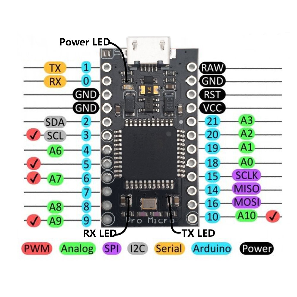
Pin mpping for Pro Micro Boards/ATMega32U4
Arduino Pro Micro: Pins explained
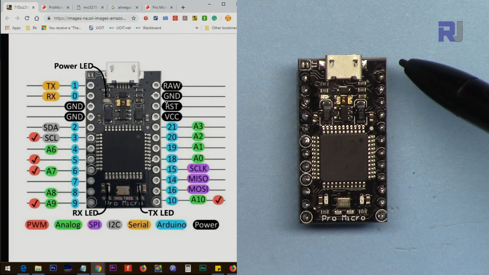
Click on image to enlarge
Arduino Pro Micro: Soldreing Pin headers
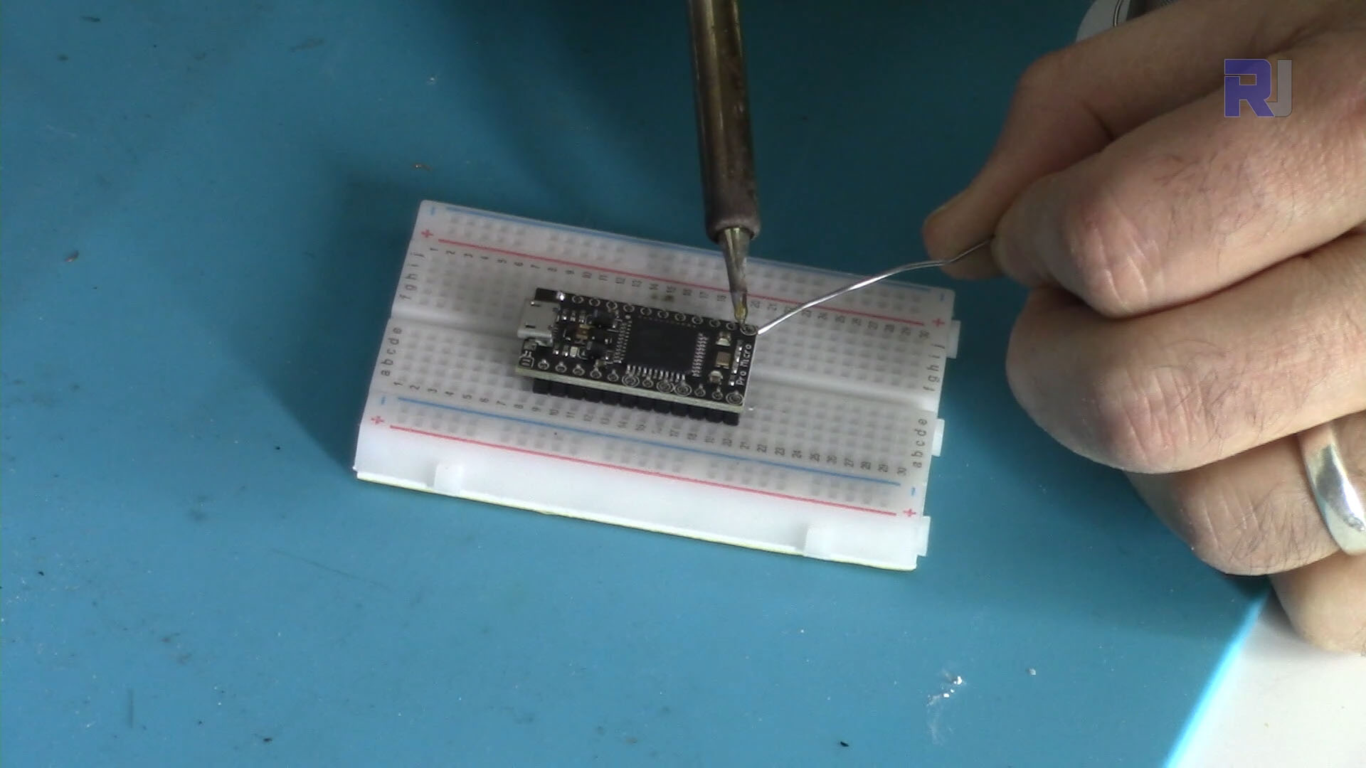
Click on image to enlarge
Arduino Pro Micro: Powering up from external source
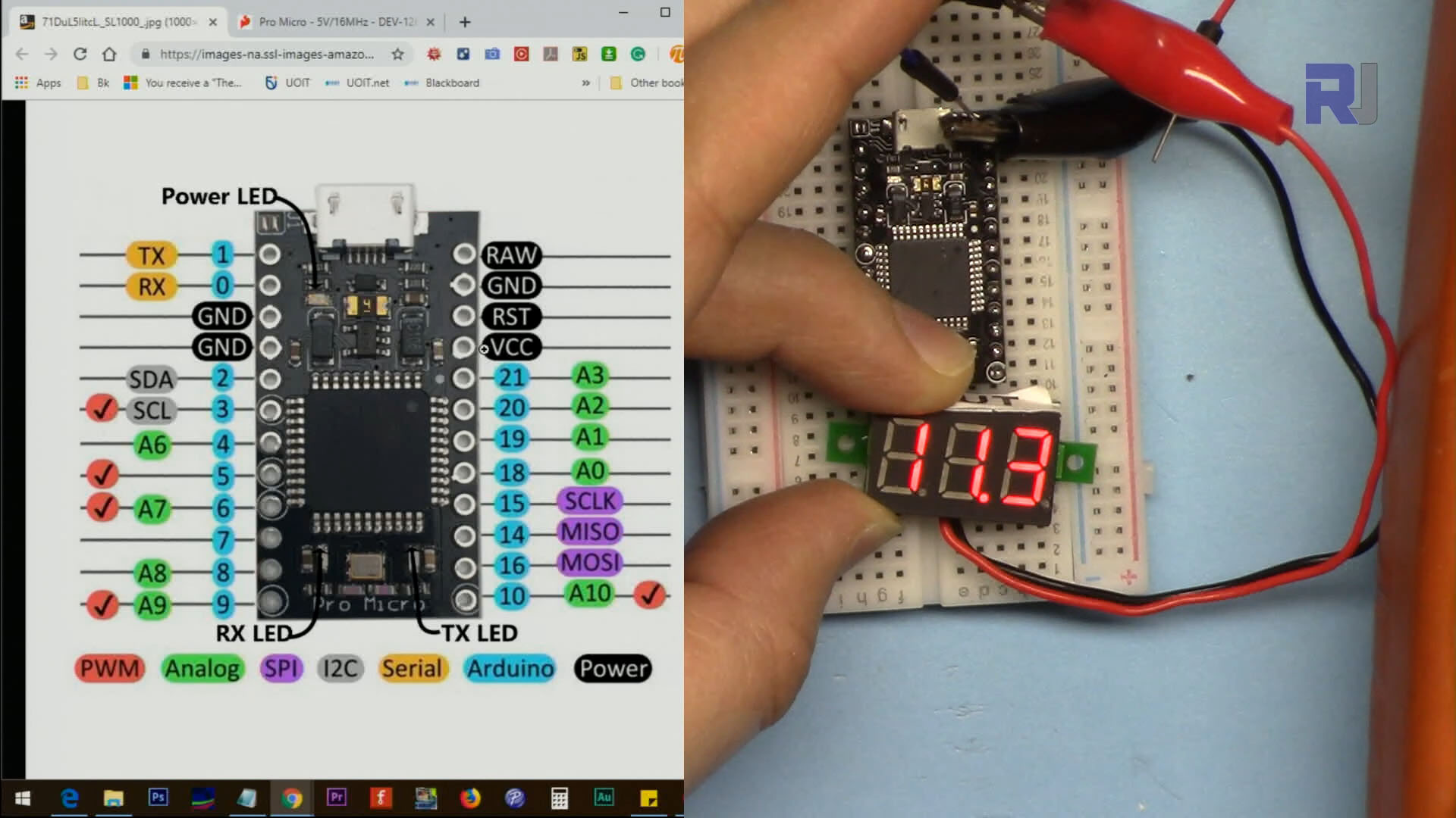
Click on image to enlarge
Arduino Pro Micro: J1 Connector explained
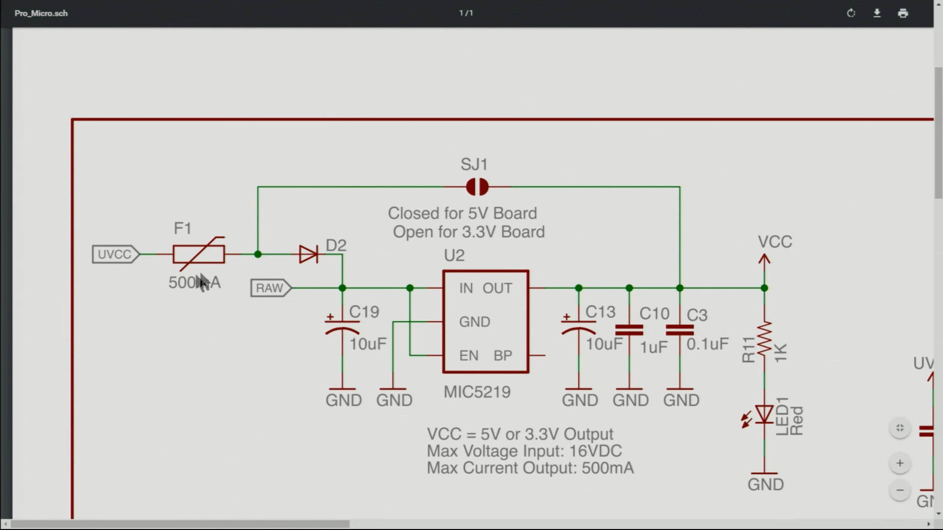
Click on image to enlarge
Arduino Pro Micro: Measuring VCC Pin voltage
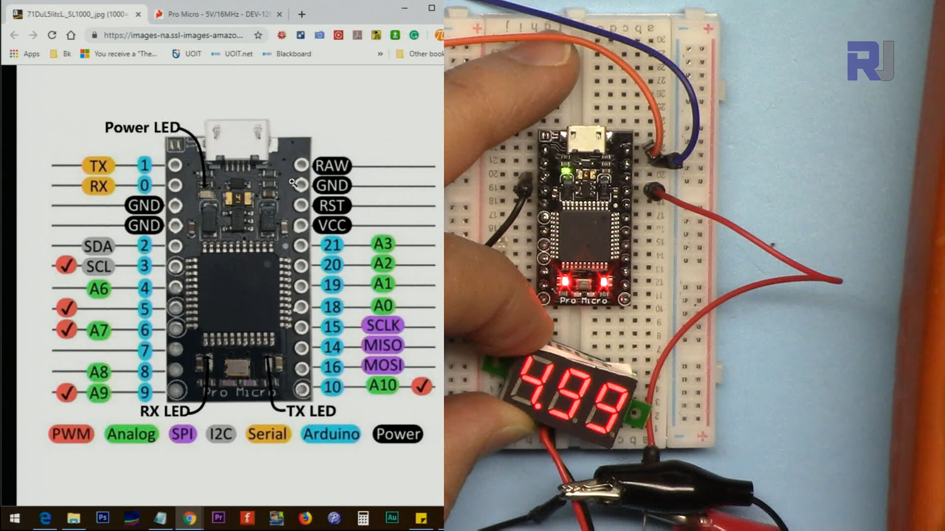
Click on image to enlarge
Arduino Pro Micro: Connecting LED to pin for Blink program
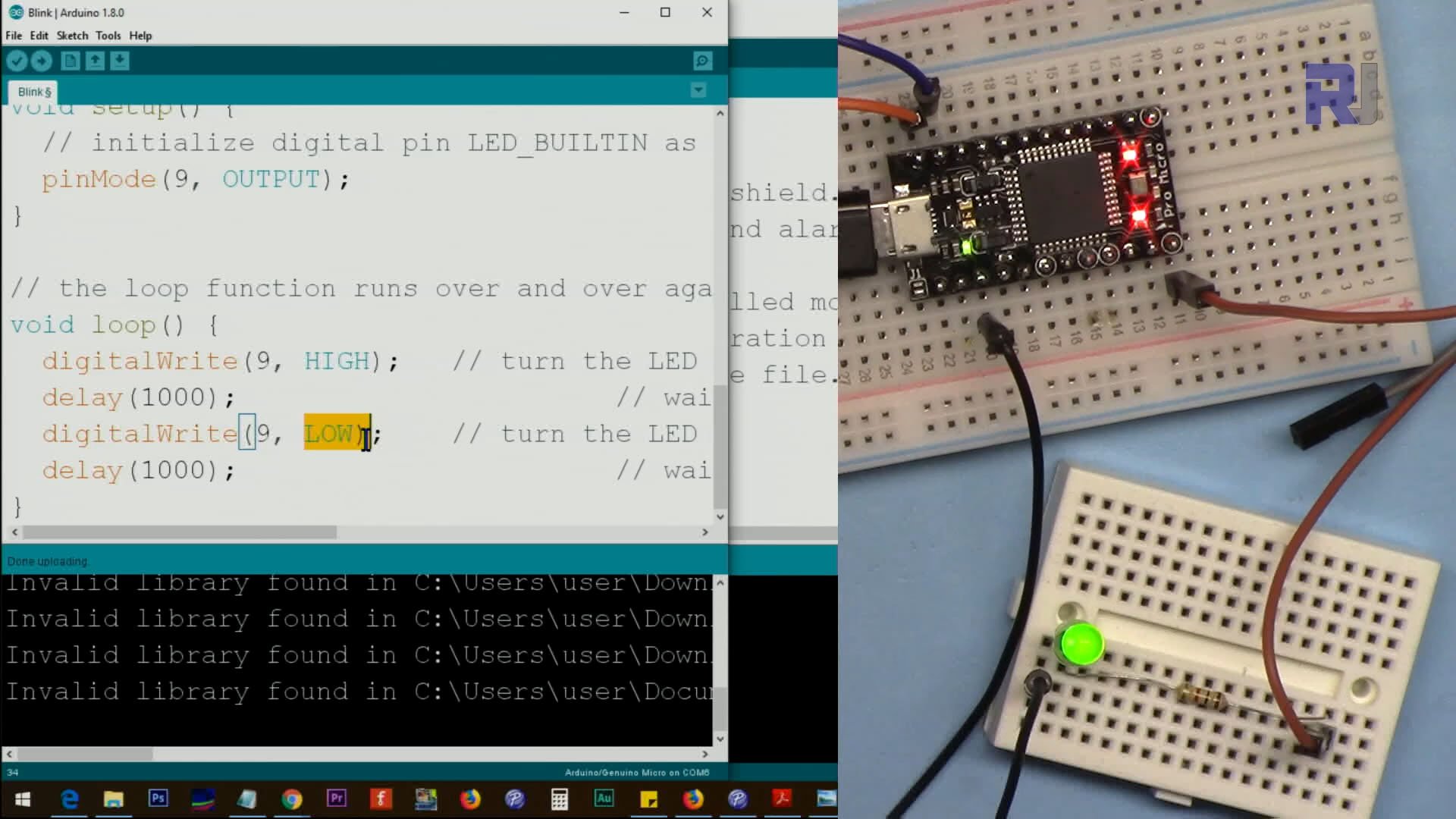
Click on image to enlarge
Arduino Pro Micro: Controlling Servo Motor
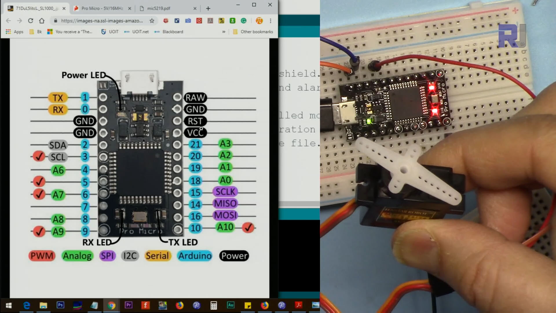
Click on image to enlarge