Review of 400W DC Step-up Boost Converter input 8.5V-50V to 10V-60V
Review of 400W DC Boost Converter input 8.5V-50V to 10V-60V
The module is explained fully with components. Minimum and maximum input and output voltage is tested. Setting Current limit is shown and tested with input and output of 9V, 12V, 15V 24V, 36V with different currents so we know how much current it can produces. Thermal image shown the hottest spot of the module. Link to resources and purchasing this module is below.
Specifications from Seleler. Test shown different. Watch video
- Input voltage: DC8.5V-50V
- Input current: 15A (MAX) exceeds 8A please enhance heat dissipation
- Quiescent current: 10mA (12V liter 20V, the output voltage, the higher the current will increase too quiet)
- Output voltage: 10-60V continuously adjustable
- Constant] range: 0.2-12A
- Temperature: -40 to + 85 degrees (ambient temperature is too high, please enhance heat dissipation)
- Operating frequency: 150KHz
- Conversion efficiency: up to 96%
- Overcurrent protection: yes
- Input reverse polarity protection: no
- Installation: 4 2.55mm screw holes
- Connection method: Connection Output
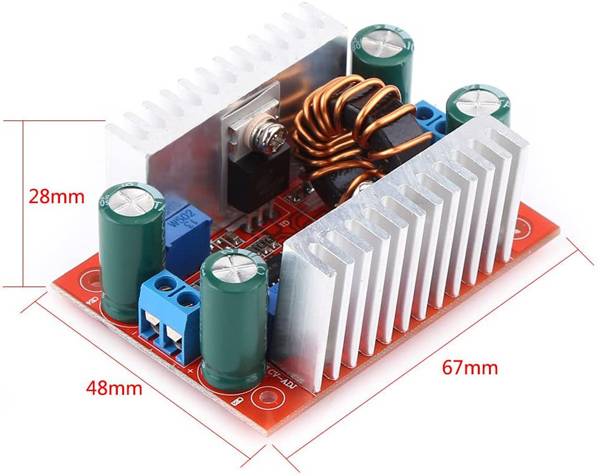
- Module size: 67mm X48mm X 28mm (LxWxH)
- RV2 is 502 (5000Ω) and RV1 is 103 (10,000 Ω)
Chapters of this video
- 01:00 Module explained
- 04:54 Components explained
- 07:10 Minimum/Maximum Voltage tests
- 09:14 Setting Current limit
- 12:46 Test Input 9V Output 12V
- 16:37 Test Input 9V Output 15V
- 18:39 Test Input 9V Output 36V
- 19:09 Test Input 9V Output 50V
- 20:21 Test Input 9V Output 60V
- 21:46 Test Input 12V Output 15V
- 22:19 Test Input 12V Output 24V
- 22:51 Test Input 12V Output 36V
- 23:18 Test Input 12V Output 50V
- 23:51 Test Input 12V Output 60V
- 24:58 Test Input 24V Output 36V
- 26:04 Test Input 24V Output 60V
- 26:32 Test Input 36V Output 50V
- 28:31 Test Input 36V Output 60V
- 29:37 Charging battery
- 33:50 Measuring Ripple Voltage
- 34:41 Conclusion Remarks
400W Step-up DC Converter: Main
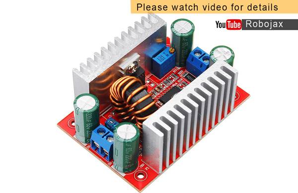
Click on image to enlarge
400W Step-up DC Converter: Connected to power supply
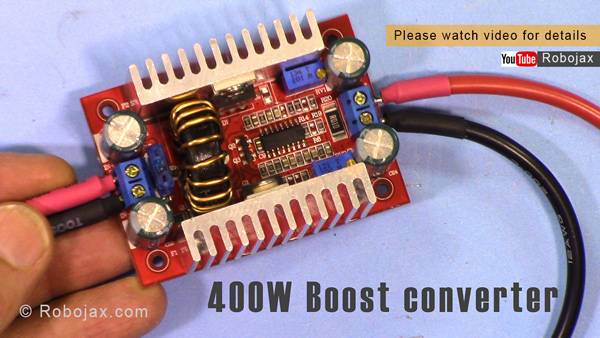
Click on image to enlarge
400W Step-up DC Converter: Oscilloscope is connected to measure ripple. Power shown
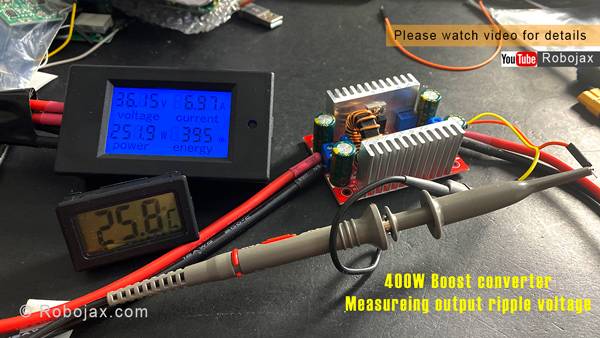
Click on image to enlarge
4400W Step-up DC Converter: Oscilloscope is connected to measure ripple
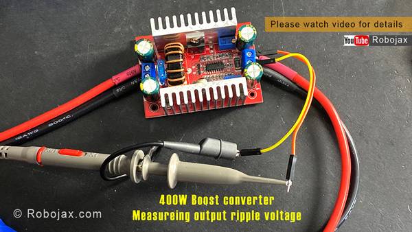
Click on image to enlarge
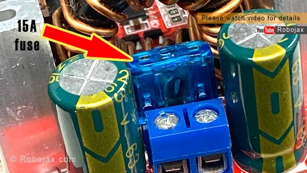
400W Step-up DC Converter: 15A Fuse at input
Click on image to enlarge
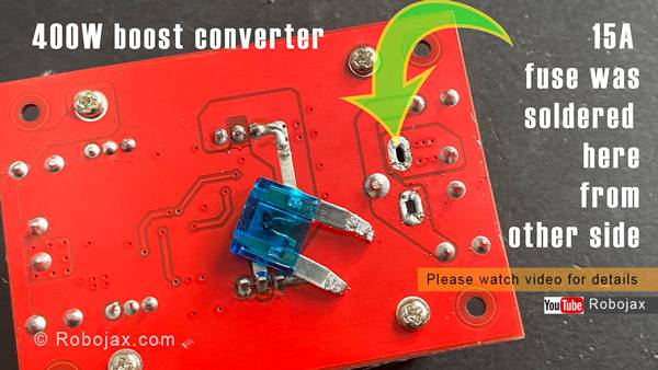
400W Step-up DC Converter: 15A fuse removed back of PCB voiew
Click on image to enlarge
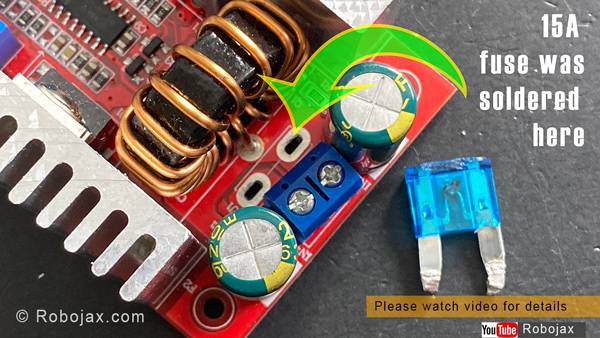
400W Step-up DC Converter: 15A fuse removed desoldered
Click on image to enlarge
400W Step-up DC Converter: Dimensions
Click on image to enlarge
Resources for this Article
- TL494 PWM Controller datasheet (pdf)
- MBR20100 CT Shottky Barrier Rectifier datasheet (pdf)
- NCE8290 N-Channel Enhansement Mode Mosfet 90A datasheet (pdf)
- SS8550 Y2 Transistor datasheet (pdf)
- Y1 SOT89 SILICON PLANARVOLTAGE REGULATOR DIODES datasheet (pdf)
- My Arduino Course on Udemy.com. Get Wiring diagram
- Get Early Access to my videos via Patreaon
- I2C Scanner
- Introduction to LCD1602-I2C with code
