VL53L0X Time-of-Flight Distance Sensor Breakout GY-VL53L0XV2V Module Arduino 4+2 Pins (blue)
The VL53L0X from ST Microelectronics is a time-of-flight ranging system integrated into a compact module. This board is a carrier for the VL53L0X, so we recommend careful reading of the VL53L0X datasheet (1MB pdf) before using this product.
The VL53L0 uses ST’s FlightSense technology to precisely measure how long it takes for emitted pulses of infrared laser light to reach the nearest object and be reflected back to a detector, so it can be considered a tiny, self-contained lidar system. This time-of-flight (TOF) measurement enables it to accurately determine the absolute distance to a target without the object’s reflectance greatly influencing the measurement. The sensor can report distances of up to 2 m (6.6 ft) with 1 mm resolution, but its effective range and accuracy (noise) depend heavily on ambient conditions and target characteristics like reflectance and size, as well as the sensor configuration. (The sensor’s accuracy is specified to range from ±3% at best to over ±10% in less optimal conditions.)
Ranging measurements are available through the sensor’s I²C (TWI) interface, which is also used to configure sensor settings, and the sensor provides two additional pins: a shutdown input and an interrupt output.
The VL53L0X is a great IC, but its small, leadless, LGA package makes it difficult for the typical student or hobbyist to use. It also operates at a recommended voltage of 2.8 V, which can make interfacing difficult for microcontrollers operating at 3.3 V or 5 V. Our breakout board addresses these issues, making it easier to get started using the sensor, while keeping the overall size as small as possible.
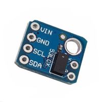
PIN Description
VDD Regulated 2.8 V output. Almost 150 mA is available to power external components. (If you want to bypass the internal regulator, you can instead use this pin as a 2.8 V input with VIN disconnected.)
VIN This is the main 2.6 V to 5.5 V power supply connection. The SCL and SDA level shifters pull the I²C lines high to this level.
GND The ground (0 V) connection for your power supply. Your I²C control source must also share a common ground with this board.
SDA Level-shifted I²C data line: HIGH is VIN, LOW is 0 V
SCL Level-shifted I²C clock line: HIGH is VIN, LOW is 0 V
XSHUT This pin is an active-low shutdown input; the board pulls it up to VDD to enable the sensor by default. Driving this pin low puts the sensor into hardware standby. This input is not level-shifted.